


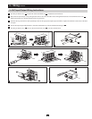
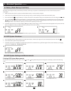

4
-
G
+
SLOT
UTILITY
INPUT
BREAKER
TB1
TB2
EXT.
BATTERY
RS232
EPO
ON OFF
S1
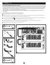
A
E F G
B
C
D H
I
J
T
o
U
P
S
B
a
t
t
e
r
y
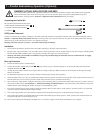
T o E x t e n d e d B a t t e r y
-
G
+
-
G
+
D C B r e a k e r
3
0
A
2
5
0
V
d
c
K
M
L
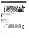
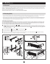
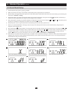
3 – Rear Panel Features
Note: Refer to Section 6-1 for a description of the UPS system’s control panel.
UPS System Power Module Rear Panel
A
RS-232Port(Note:RemovethenetworkcardinordertousetheRS-232port.)
B
Settings Switch for Parallel Redundancy Operation
C
CANBusConnectionPortsforParallelRedundancyOperation
D
Cooling Fans
E
ExternalBatteryPackDCCableConnector
F
UtilityInputBreaker
G
Ventilation Openings
H
Input/OutputTerminalBlock
I
EPO (Emergency Power Off) Connection
J
NetworkCard
External Battery Pack Rear Panel
K
UPSPowerModuleDCCableConnector
L
ExternalBatteryPackDCCableConnector(ForAdditionalExternalBatteryPacks,SoldSeparately)
M
DCBreaker