


3
Features
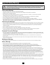
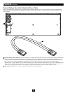
The UPS system includes a power module, an external battery pack and an independent, detachable PDU with a manual bypass switch. When
the switch is set to bypass, the PDU can be completely removed from the power module for power module maintenance, repair or replacement
without disrupting power to connected loads. Review the location and function of the UPS system's features before installing and operating it.
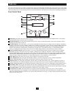
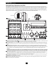
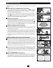
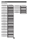
Front Control Panel
I/P BYPASS
BATTERY AC/DC DC/AC O/P
OFFON
MUTE SELECT
SETUP
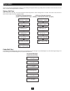
LCD Display: This backlit dot matrix display indicates a wide range of UPS operating conditions and diagnostic data. It also displays
UPS settings and options when the UPS is in setup mode.
“ON/MUTE” Button: Press this button and hold it until you hear a beep to turn the UPS system's inverter ON. If the battery alarm is
sounding, press this button to silence it.
Scroll Down Button: This button allows you to browse through different options and power readings on the LCD display. Momentarily
pressing it causes the LCD screen to display a different power reading (see “Operation” section). Pressing it and the SCROLL UP Button
together puts the UPS in setup mode, where this button is used to scroll through setup options and to exit setup mode. Pressing the
SCROLL UP and SCROLL DOWN buttons simultaneously for longer than 1 second while the UPS is in “ON BATTERY MODE”
allows you to change the output voltage of the UPS (refer to “Output Voltage Selection” in the “Operation” section for details).
Scroll Up/“SELECT” Button: This button allows you to browse through different options and power readings on the LCD display.
Momentarily pressing it causes the LCD screen to display a different power reading (see “Operation” section). Pressing it and the
SCROLL DOWN Button together puts the UPS in setup mode, where this button is used to select setup options. Pressing the SCROLL
UP and SCROLL DOWN buttons simultaneously for longer than 1 second while the UPS is in “ON BATTERY MODE” allows you to
change the output voltage of the UPS (refer to “Output Voltage Selection” in the “Operation” section for details).
“OFF” Button: Press this button until you hear a beep to turn the UPS system's inverter OFF.
“O/P” (Output) LED: This green light will illuminate to indicate your UPS is supplying AC power to connected equipment.
“DC/AC” (Inverter) LED: This green light will illuminate to indicate the DC/AC inverter is activated.
“BYPASS” LED: This green light will illuminate when the UPS is providing filtered mains power without engaging its converter or
inverter. If this LED is lit, connected equipment will not receive battery power in the event of a blackout or other power interruption.
“AC/DC” (Converter) LED: This green light will illuminate to indicate the AC/DC converter is charging the connected battery pack(s).
“BATTERY” LED: This red light will illuminate when the UPS is discharging the battery to provide connected equipment with AC
power. An alarm will sound which can be silenced by pressing the ON/MUTE Button. This LED will remain lit after the alarm is silenced.
“I/P” (Input) LED: This green light will illuminate to indicate an AC input supply is present.
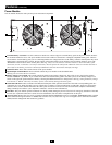
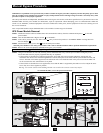
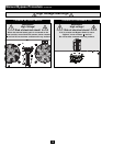
Control Panel Access Slots: The control panel can be adjusted to match the orientation of the UPS system. (1) Insert a flathead
screwdriver into the access slots and gently lever the control panel away from the front panel of the UPS system. (2) Rotate the control
panel to the desired orientation. DO NOT twist or pull the control panel cables excessively. (3) Gently reinsert the control panel into the
front panel of the UPS system.
1
2
3
4
5
6
7
8
9
10
11
12
1
2
3
4
5
6
7
8
9
10
11
12
12