


8
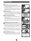
Connection
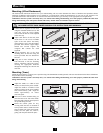
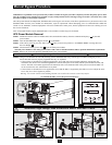
Attach the PDU to the Power Module and Battery Pack.
Align and connect the PDU's power module terminal block with the input/output terminal
block on the back of the power module. Secure the PDU to the power module with four
screws. Before proceeding, ensure that the bypass switch is set to NORMAL. Remove the
utility input terminal block cover .
Hardwire the PDU to a Utility Power Source.
Pass user-supplied cabling through the knockouts on the top of the PDU and connect
it to the PDU's input terminals . Replace the terminal block cover. Connect the other
end of the cabling to a dedicated utility power circuit of sufficient amperage.
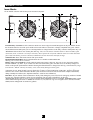
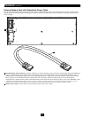
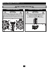
Connect the Battery Pack to the Power Module.
Consult the owner’s manual that came with the battery pack. Remove the retention
brackets from the power module's battery connector and one of the battery pack's
rear panel connectors . Attach one end of the detachable battery power cable to each
connector. (Small sparks may occur; this is normal.) Reattach the retention brackets
immediately to the right of each connector, using the additional screw holes provided to
the right of the original bracket position. The brackets will secure the battery power cable
connection. Warning: Always use the connector retention brackets to secure the
battery pack connection. Do not attempt to operate the UPS system without the
connector retention brackets in place. NOTE: the power module does not contain
internal batteries and will not
start until a battery pack is connected. Allow the battery to
charge for at least 12 hours to ensure full battery backup for connected equipment. If you
require increased battery backup runtime, an unlimited number of additional external
battery packs may be daisy-chained to the primary battery pack. Adding additional external
battery packs will increase runtime battery backup runtime, but it will also increase
recharge time.
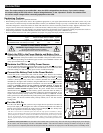
Turn the UPS On.
Press the “ON” Button until you hear a beep to begin inverter operation. The UPS will
now provide output power through its AC outlets to connected equipment. The UPS will
perform a brief self-test and show the results on the LCD Display . See “Startup Self-
Test” in the “Operation” section for the display sequence.
Cold Start: To use the UPS as a stand-alone power source when AC input power is unavailable (i.e. during a
blackout), you can cold start the UPS and power connected equipment from the battery. The battery must be at least
partially charged for this operation to succeed. Press and hold the “ON” Button until you hear a beep to cold start
the UPS. The LCD Display will show “ON BATTERY MODE”. Battery power will begin discharging. Some
electronic equipment may draw more amps during startup; when cold starting, consider reducing the initial load on
the UPS.
K
J
I
HG
FE
D
C
B
A
1
2
J
K
4
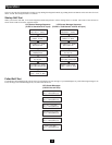
Note: The output voltage is set at 208/120V~ when the UPS is shipped from the factory. If you need to change
the output voltage of the UPS, refer to “Output Voltage Selection” in the “Operation” section. You should select
the correct output voltage before connecting equipment to the UPS.
1
2
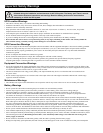
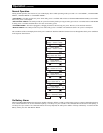
Hardwiring Cautions
• Wiring must be installed by a qualified electrician.
• When making wiring connections, observe the regulations appropriate to your region [National Electrical Code (NEC) in the U.S.] at all
times. Be sure to install an easily accessible disconnect switch in your installation wiring so you may cut off the UPS AC input during fires
and other emergencies. Ensure that cables are fitted with cable sleeves and are secured by connector clamps. Tighten connections with a
torque of not less than 24-28 inch-pounds (2.7-3.2 newton-meters). Make sure that your equipment is properly grounded.
• Using cables of improper size may damage your equipment and cause fire hazards. Choose appropriate cabling and protection circuits to
make wiring connections. Ground conductors must be the same size and type as the power conductors used.
• Refer to National Electrical Code (NEC) guidelines for proper wire gauge and output protection circuit requirements.
A
3
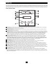
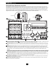
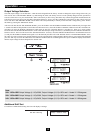
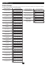
Contacts on Power Module and PDU
WARNING! High Voltage! Risk of electrical shock!
Do not let these contacts touch any surface!
See "Manual Bypass Procedure" section for more information.
4
3
B
C
D
F
E
G
H
I
Input and Output Ratings
Input Maximum Rated Maximum Rated Typical
Model Voltage Input Current Output Current Wire Size
SU16000RT4U 100-140V (L1-N: L2-N) 68A 70A 4 AWG
SU16000RT4UHW 100-140V (L1-N: L2-N) 68A 70A 4 AWG
To Turn the UPS System OFF: Press the UPS's “OFF” Button until you hear a beep. The UPS will stop providing output power through
its AC outlets. The LCD Display will show “STANDBY MODE.” The UPS will continue to charge its batteries as long as AC input
power is present. To completely deactivate the UPS, disconnect the UPS from AC input power when the UPS system is in standby mode.