


9
Optional Connection
The following connections are optional. The UPS system will function properly without these
connections.
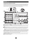
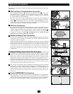
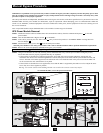
USB and Serial Communication Connection
Use the included USB cable and/or RS-232 DB9 serial cable to connect the
communication port of a computer to the communication port of the UPS. Install the
PowerAlert Software appropriate for the computer’s operating system. Consult the
PowerAlert manual for more information.
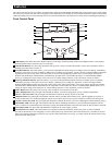
Dry Contact Note: Dry contact communications are simple, but some knowledge of
electronics is necessary to configure them. The DB9 port's pin assignments are shown in
diagram . If the UPS battery is low, the UPS sends a signal by bridging pins 1 and 5.
If utility power fails, the UPS sends a signal by bridging pins 8 and 5. To shut the UPS
down remotely, short pin 3 and pin 9 for at least 3.8 seconds.
EPO Port Connection
This optional feature is only for those applications that require connection to a facility's
Emergency Power Off (EPO) circuit. When the power module is connected to this circuit,
it enables emergency shutdown of the UPS system’s output. Using the included cable ,
connect the EPO port to a user-supplied normally open switch. The pin assignment for
the EPO port is shown in diagram . The EPO port is not a phone line surge
suppressor; do not connect a phone line to this port.
2b
2a
1c
1b1a
1
2
1a
1b
2a
2b EPO Pin Assignment
3a
3b
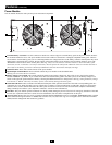
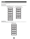
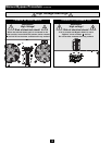
Additional Battery Pack Connection
The UPS system includes one external battery pack. Additional external battery packs are
not required to operate the UPS system, but they will provide additional battery backup
runtime for connected equipment.
Connect multiple battery packs by daisy-chaining the second to the first, daisy-chaining
the third to the second and so on. Note: When daisy-chaining multiple battery packs, they
should be identical models of similar age and level of wear. Make sure that cables are
inserted fully into connectors. Small sparks may occur during battery connection; this is
normal. Do not connect or disconnect battery packs when the UPS is operating from
battery power. Multiple battery packs provide longer runtimes, but also require longer
recharge times.
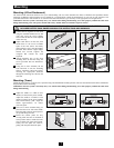
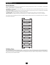
Additional Battery Pack Connection Procedure
(1) Remove the retention bracket from one of the first battery pack’s rear panel
connectors. (The other connector will already be attached to the power module or another
battery pack.) (2) Insert one end of the detachable power cable into each battery pack,
making sure to insert the cable connectors into the battery pack connectors fully. (3)
Attach the retention brackets to the right of each connector, using the screw holes set to
the right of the original bracket position. Warning: Always use the connector retention
brackets to secure the battery pack connections. Do not attempt to operate the UPS
system without the connector retention brackets in place.
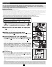
If two or more external battery packs (including the external battery pack that is included
with the UPS system) are connected to the UPS system, move the Battery Charge Level
Switch from the default position (labeled “NORMAL”) to the right-hand position
(labeled “HIGH”). Warning: Setting the Battery Charge Level Switch to “HIGH” with
only one external battery pack connected to the UPS system may damage the external
battery pack.
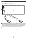
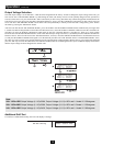
Internal SNMP/WEB Card Insertion
Remove the slot's cover to install an optional internal SNMP/Web accessory card (Model:
SNMPWEBCARD) to enable remote UPS monitoring and control via SNMP, Web or
telnet. Contact Tripp Lite Customer Support at (773) 869-1234 for more information,
including a list of available SNMP, network management and connectivity products.
3
4
1c
4
3a
3b