


Mounting (4-Post Rackmount)
The UPS includes rackmount shelf kits for 4-post rackmounting. The user must determine the fitness of hardware and procedures before
mounting. If hardware and procedures are not suitable for your application, contact the manufacturer of your rack or rack enclosure. The
procedures described in this manual are for common rack and rack enclosure types and may not be appropriate for all applications.
WARNING! The UPS system is extremely heavy. Use caution when lifting and mounting. User must properly stabilize the UPS when
lifting and mounting. Note: The power module and battery module must be installed in separate shelves.
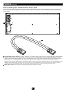
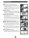
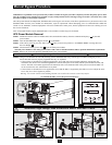
Connect the two segments of each shelf
using the included attached screws and
wing nuts. Leave the screws slightly
loose so that the shelves can be adjusted
in the next step.
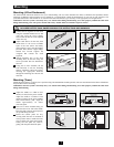
Adjust each shelf to fit the rack, then
mount them in the lowest available
space of the rack (above the battery
pack) with the screws, nuts and washers
provided. Note that the support ledges
should face inward. Tighten the
wingnuts that connect the shelf
segments.
Attach mounting ears to the front
mounting holes of the UPS using the
screws provided. The ears should face
forward.
Using one or more assistants, lift the
UPS and slide it onto the mounting
shelves. Attach the UPS to the rack by
inserting the appropriate hardware
through the mounting ears and into the
rack rails.
7
Mounting
3
2
1
4
Mounting (Tower)
Mount the UPS system in a vertical, tower position using 2-9USTAND base stands (optional). The user must determine the fitness of hardware
and procedures before mounting.
WARNING! The UPS system is extremely heavy. Use caution when lifting and mounting. User must properly stabilize the UPS when
lifting and mounting.
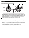
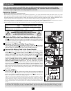
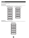
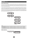
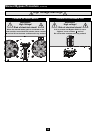
Adjust the stands to a width of 6.93
inches (176 mm) for the power module.
Adjust the stands to a width of 13.86
inches (352 mm) for the power module
and external battery pack. Align the
stands approximately 10 inches
(254 mm) apart.
Have one or more assistants help you
place the UPS on its side in the stands.
Place the UPS so that its control panel is
on top and facing outward.
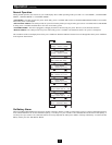
Rotate the control panel for easy
viewing while the UPS is mounted in
tower position. Insert a small tool in the
slots on either side of the control panel.
Gently lever the panel out; rotate it;
gently push the panel back into place.
1
3
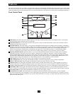
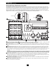
I/P
BYPASS
BATTERY
AC/DC DC/AC
O/P
OFF
ON
MUTE
SELECT
SETUP
3
1
2
3
4
10 in.
(254 mm)
2
INSTALL THE 4U EXTERNAL BATTERY PACK BEFORE INSTALLING THE POWER MODULE. SEE THE
INCLUDED BATTERY PACK OWNER'S MANUAL FOR INSTRUCTIONS AND WARNINGS.
2
1 Power Module
6.93 in. (176 mm)
1 Power Module +
1 Battery Pack
13.86 in. (352 mm)
1
1