74 Chapter 3: Replacing Pre-Installed Components
4. Place a new USB board in position in the chassis follow-
ing the above steps in reverse.
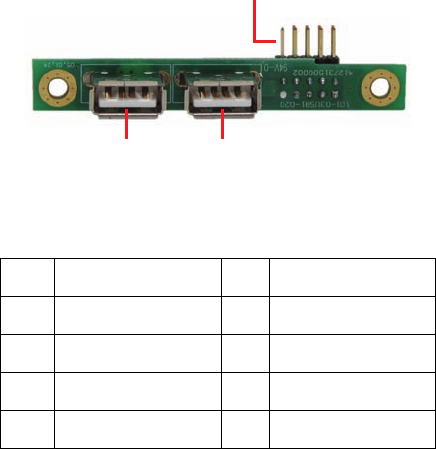
3.6.1 USB Board Features
3.6.2 USB Board Connector Pin Definition
2 x 5 Pin USB Header
1 USB1 POWER 2 USB2 POWER
3 USB1 DATA - 4 USB2 DATA -
5 USB1 DATA + 6 USB2 DATA +
7 USB1 GND 8 USB2 GND
9 KEY PIN 10 NONE
USB 2x5 pin Header
USB1 USB2


