


WFS709TP ProSafe Smart Wireless Switch Hardware Installation Guide
1-6 Introduction
v1.0, May 2007
The port accepts an RS-232 serial cable with an RJ-45 male connector. See “Serial Console Port”
on page A-3 for more port and cable specifications.
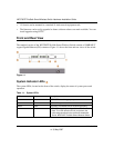
Fans/Heat Exhaust
Three independent fans located on the side of the chassis promote proper air circulation for cooling
the WFS709TP ProSafe Smart Wireless Switch.
During operation, the air vents on the left and right sides of the chassis must remain unobstructed
by cables or mounting equipment. For proper air circulation, leave at least 10 cm (4
inches) of
clearance on the left and right of the chassis.
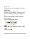
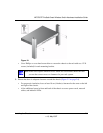
Rack Mounting Brackets
Mounting brackets are attached to each side of the chassis.
Power Input Socket
The power input socket on the chassis rear panel accepts a power cord with a standard IEC320
connector. For proper safety and performance, the power cord must be rated to 10 A and must
conform to grounded electrical standards in the country in which the switch operates.
Task Overview
As with any full-featured network equipment, deployment may involve multiple components as
well as various individuals in your organization. As the network manager, you should become
familiar with the components and deployment summary outlined in the following sections.
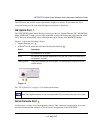
NETGEAR Smart Wireless Components
Familiarize yourself with these three major components:
• WFS709TP Switch. This is an enterprise-class switch into which multiple access points (APs)
are connected and controlled. NETGEAR Wireless Access Points designed for small and mid-
sized businesses with enterprise-class features can function as either access points or air
monitors.
5
6
7