


3-18 Installation and Replacement
Cabling the Vanguard 342
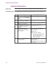
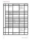
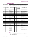
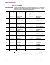
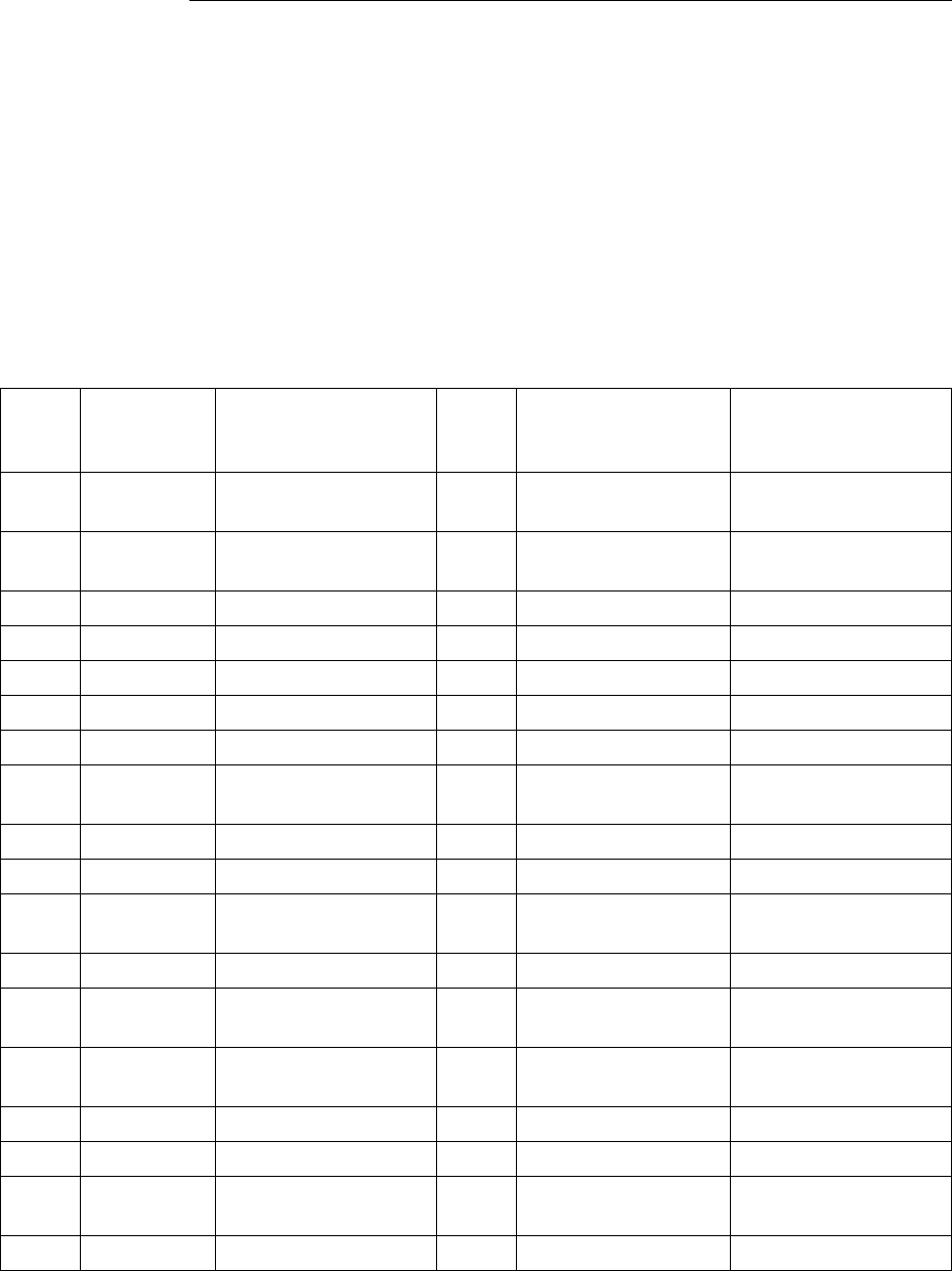
DB25 V.24 Pinouts
Connector Pinouts This table shows the DB25 V.24 connector pinouts for DCE/DTE mode. To use DTE
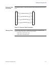
to DTE or DCE to DCE mode, a crossover adapter cable is required. Refer to
Figure 3-5 on page 3-21 for crossover cable connections.
These pins are assigned double functions in the V.24 cable:
• Pin 15: Outputs TRANSMIT CLOCK if the port is configured for internal
clocks. Otherwise it acts as a V.54 Loop 1 signal when connected to a modem.
• Pin 22: Used as the Ring Indicator output if the port is configured to emulate a
dial modem. For this to work properly, the RI/TM port must be configured to
RI. When the RI/TM is configured to TM, this pin acts as an input, and the
TM output from the attached modem (pin 25 on the modem) comes into the
Vanguard on this pin.
For more information on configuring the V.24 interface type, refer to the “Setting the
Interface Type” section on page 3-9.
Port 3
Pin
DCE
Signal
Function/Signal
Name
Port 3
Pin
DTE Signal using
Crossover
Adapter Cable
Function/Signal
Name
1 -------------- PROTECTIVE
GROUND
1 -------------- PROTECTIVE
GROUND
2 <------------ TRANSMITTED
DATA
2 ------------> TRANSMITTED
DATA
3 ------------> RECEIVED DATA 3 <------------ RECEIVED DATA
4 <------------ REQUEST TO SEND 4 ------------> REQUEST TO SEND
5 ------------> CLEAR TO SEND 5 <------------ CLEAR TO SEND
6 ------------> DATA SET READY 6 <------------ DATA SET READY
7 -------------- SIGNAL GROUND 7 -------------- SIGNAL GROUND
8 ------------> DATA CARRIER
DETECT
8 <------------ DATA CARRIER
DETECT
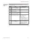
14 <------------ DATA RESTRAINT 14 ------------> DATA RESTRAINT
15 ------------> TRANSMIT CLOCK 15 <------------ TRANSMIT CLOCK
16 ------------> STANDBY
INDICATOR
16 <------------ STANDBY
INDICATOR
17 ------------> RECEIVE CLOCK 17 <------------ RECEIVE CLOCK
18 <------------ EXTERNAL
RECEIVE CLOCK
18 ------------> EXTERNAL
RECEIVE CLOCK
20 <------------ DATA TERMINAL
READY
20 ------------> DATA TERMINAL
READY
21 <------------ V.54 Loop 1 21 ------------> V.54 Loop 1
22 ------------> TEST MODE 22 <------------ TEST MODE
24 <------------ EXTERNAL
TRANSMIT CLOCK
24 ------------> EXTERNAL
TRANSMIT CLOCK
25 <------------ MAKE BUSY 25 ------------> MAKE BUSY