


PART 2. FUNCTION SELECTION FOR DATA TRANSMITTING AND
RECEIVING UNITS
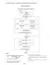
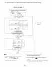
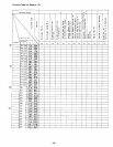
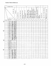
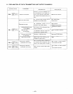
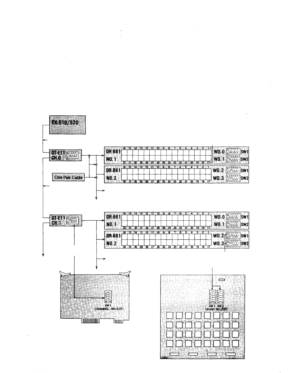
8. SETTING CHANNEL SELECT SWITCHES OF TRANSMITTING UNITS (DT-E11) AND WORD
SELECT SWITCH OF RECEIVING UNITS (DR-B61)
NOTE
1. Connect the DT-E11 and DR-B61 to Exchange cor-
rectly. (Refer to installation manuals of DT-E11 and
DR-B61.)
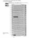
2. Set the function select switches (DIP SWITCH) on
CPU-55 correctly and be sure to enter initial pro-
gramming and function registration at programming
station No. 200.
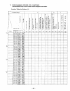
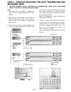
3. Remove the front panel of Data Transmitting Unit
(DT-E11) and take out the printed circuit board. Then
set the channel select switches located on the printed
circuit board, according to the necessary functions
such as IN/OUT Annunciation, Calling Party Indication
etc, and replace in the Unit.
(Refer to 12. Explanation of Data Transmitting Unit
Output Channels, Page 39).
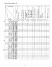
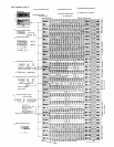
4. The DT-E11 sends out 512 bit data (16 bit x 32 words)
to control relays on Data Receiving Unit (DR-B61).
Therefore set the two word select switches on DR-B61,
according to necessary output mode. SW-1 is for
Relay No.1 to No.16 and SW-2 is for Relay No.17 to
No. 32. See Page 41 for details.
(Refer to Explanation of Data Receiving Unit Output
Channels.)
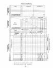
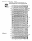
Relay Number
Connecting
Cable YR-802
Connecting
Cable
YR-803
To other DR-B61
To other
DT-E11
CHANNEL SELECT
Switch (SW-1)
To other DR-B61
WORD SELECT
Switch
(SW-1, SW-2)
– 43 –