17
3.3.2 POWER FUSE
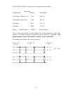
The SYSTEM 32 power supply is not fused. An external 1/2 AMP fuse in
the AC input line is recommended.
4.0 COMMUNICATIONS SET-UP AND CONNECTIONS
The ANAFAZE SYSTEM 32 is designed for three types of serial communications:
RS-232, RS-485, and 20ma current loop. Up to 16 units can be connected on one
communication line.
4.1 RS-232
The optically-isolated RS-232 interface is located on the processor module A32-
PIOM. Multiple SYSTEM 32 units are connected in parallel. Connections are
made on the upper terminal block TB1 as follows:
Computer SYSTEM 32 [1] SYSTEM 32 [2]
TB1 TB1
RX #3 ----------- TX- #2 ------------ TX- #2
TX #2 ----------- RX+ #3 ------------ RX+ #3
GND #7 ---------- RX- #4 ------------ RX- #4
The computer pins are for the normal 25 pin RS-232 connector. On some
computers transmit TX and receive RX may be reversed. Please check your
computer manual for details.
The ANAFAZE SYSTEM 32 RS-232 interface transmits data on TX- and receives
data on RX+. The host computer TXD output should be connected to the SYSTEM
32 RX+ input. The SYSTEM 32 TX- output should be connected to the host
computer RXD input. Host computer communication ground should be connected
to the SYSTEM 32 RX-.
Multiple SYSTEM 32 units are connected on the RS-232 line in parallel. The
SYSTEM 32 nearest to the computer is connected as described above. Then each
SYSTEM 32 is daisy chained wire for wire to the next unit. The next units' TX- is
connected to the first units' TX-, RX+ to RX+, and RX- to RX- etc.
WARNING: REMOVE JUMPER FOR MULTIPLE SYSTEM 32
INSTALLATIONS
Jumper JU18 must be removed on all but the farthest unit from the
computer when multiple units are on the same communications line.


