36
6.3 ANALOG OUTPUT MODULE A32-AOM
Analog control outputs are provided for the SYSTEM 32 by using the A32-AOM.
Each module provides 16 analog outputs and up to two modules can be used in a
single SYSTEM 32 for 32 control outputs.
The AOM provides both 4 to 20ma with 400 ohms maximum load and 0- 5vdc at
5ma maximum. Both are available at the output terminals and either may be
selected.
WARNING: Both outputs may not used at the same time on the same
loop. THE OUTPUTS WILL BE IN ERROR.
WARNING: The grounds of all the analog outputs on a single
module are connected together. Ground loop problems and potential
damage can result if the outputs are connected to devices that have
common mode or other voltages on their terminals. Contact
ANAFAZE for isolated outputs.
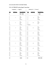
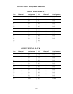
6.3.1 Typical Connections
The output connections are designated as C for the positive terminal of the
current loops along with the loop number and the negative side of the
current loop is to any of the terminals labeled NEG.
The positive output connections for the voltage loops are V along with the
loop number and the negative side is to any of the terminals labeled NEG.
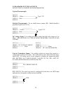
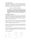
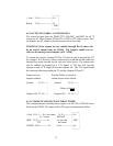
Typical Analog Output Connections are:
Function TB1 Pin#
|--------------|
PID LOOP 1C [17C] POS 6 O----------------------- + |
[4 to 20ma] | I/P |
| Converter |
NEG 5 O----------------------- - |
|--------------|
TB2 Pin#
|---------------|
PID LOOP 13V [29V] POS 20 O------------------ + Motor |
[0 to 5v] | Speed |
| Controller |
NEG 21 O------------------ - |
|---------------|


