31
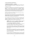
6.0 CONTROL OUTPUTS
Control outputs are provided from the A32-PIOM -- PROCESSOR I/O MODULE
for digital outputs and the A32-AOM -- ANALOG OUTPUT MODULE for
analog outputs. The A32-AOM is not required for systems that do not need
analog outputs. The A32-PIOM provides the digital control outputs, the serial
communication, and miscellaneous digital inputs and outputs.
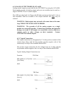
WARNING -- GROUND LOOP POTENTIAL
The ground of every control output is connected to the ANAFAZE 32
PID logic ground. Use caution when connecting external devices that
may have their low side at a voltage other than controller ground,
since potential ground loops can be created. Use isolated relays or the
isolated control device inputs if possible grounding problems are
expected.
6.1 PROCESSOR I/O MODULE
Most PROCESSOR I/O MODULE [PIOM] connections are provided on plug in
terminal blocks. Additional inputs and outputs are provided on ribbon cable
connectors. The control outputs are also available on ribbon cable connectors to
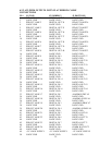
simplify external wiring. The pins used on the ribbon cable connectors can be to
connect these inputs and outputs to external terminal strips or standard I/O
module boards such as the Gordos PCB24.
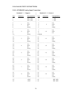
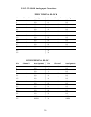
TB1 IS THE UPPER TERMINAL BLOCK and TB2 IS THE LOWER
TERMINAL BLOCK. J1, J2, and J3 ARE CONNECTORS FOR RIBBON
CABLES. These connectors can be used to reduce point to point wiring and must
be used for the additional input and output connections.
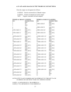
Output 65 is used by the controller to indicate a high deviation alarm and output
66 to indicate a low deviation alarm. Output 67 is used by ANASOFT 32 to
indicate a computer determined high process alarm and output 68 for the
corresponding low alarm.
Typical control outputs utilize external optically-isolated solid-state relays. These
relays use a 3 to 32vdc input for control and can be sized to switch up to 50 amps
at 480vac. For larger currents these relays can be used to drive contactors.
Connections are made as follows:
Upper Terminal Block TB1
SSR 1 SSR 2
|--------| |--------|
Pin | - + | | - + |
|--|--|--| |--|--|--|
Out 1 5 O-----------------| | | |
| | |
Out 2 6 O--------------------|------------| |
| |
+5V 11 O--------------------o---------------|


