


28
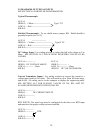
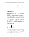
5.9 DIAGRAMS OF TYPICAL INPUTS
SEE SECTION 5.6 FOR DETAILED INFORMATION.
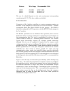
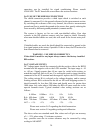
Typical Thermocouple
AUX O
HIGH O-- + White ------------------------- Type J T/C
LOW O-- - Red ----------------------------
SHLD O
Shielded Thermocouple: To use shield remove jumper RD. Shield should be
grounded at probe [see 5.6.2].
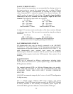
AUX O ---------------------
HIGH O-- + Yellow ------------------------- Type K T/C
LOW O-- - Red ------------------------------
SHLD O--------------------------------------
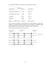
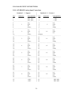
DC Voltage Input: Use scaling resistors to reduce the full scale voltage to 0 to
60mv. SEE SECTION 5.6.3 FOR SCALING RESISTORS VALUES OF RA
AND RB.
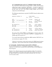
AUX O------------ + AUX O
HIGHO DC VOLTAGE ABOVE HIGH O------------- +
LOW O------------ - 60mv LOW O------------- - 60mv
SHLD 0 SHLD O DC VOLTAGE BELOW
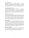
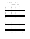
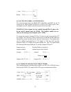
Current Transmitter Inputs: Use scaling resistors to convert the current to a
voltage input scaled to 0 to 60mv. This will result in a 0 to 20ma full scale range,
and an Mx + B scaling can be in the computer to display the engineering units.
SEE SECTION 5.6.5 FOR SCALING VALUES OF RA, RB, AND RC.
SCALING RESISTORS MUST BE INSTALLED.
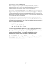
AUX O------------- +
HIGH O DC CURRENT INPUTS
LOW O------------- -
SHLD O
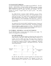
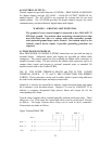
RTD INPUTS: The input loop must be configured for the three wire RTD input
and must have the proper scaling resistors installed.
AUX O-------------
HIGH O------------- RTD
LOW O-------------
SHLD O-------------