


7. Operation
..............................................
7-1
7.1. Any-to-Any Mode
......................................
7-1
7.1.1. Port Connection and Disconnection
.......................
7-1
7.1.1.1. Connecting Ports
.............................
7-1
7.1.1.2. Disconnecting Ports
...........................
7-2
7.1.2. Defining Hunt Groups
...............................
7-3
7.2. Passive Mode
.........................................
7-4
7.3. Buffer Mode
..........................................
7-4
7.3.1. Reading Data from Buffer Mode Ports
......................
7-5
7.3.2. Port Buffers
.....................................
7-5
7.4. Modem Mode
.........................................
7-6
8. Saving and Restoring Configuration Parameters
......................
8-1
8.1. Sending Parameters to a File
................................
8-1
8.2. Restoring Saved Parameters
.................................
8-2
9. Command Reference Guide
...................................
9-1
9.1. Command Conventions
...................................
9-1
9.2. Command Response
.....................................
9-2
9.3. Command Summary
.....................................
9-3
9.4. Command Set
.........................................
9-4
Appendices:
A. RS232 Port Interface......................................Apx-1
B. Specifications ..........................................Apx-2
C. Customer Service ........................................Apx-3
Index .................................................Index-1
List of Figures
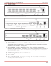
2.1. Instrument Front Panel (Model APS-16 Shown)
.......................
2-1
2.2. Instrument Back Panel (Model APS-16)
............................
2-2
2.3. Instrument Back Panel (Model APS-8)
.............................
2-2
2.4. Instrument Back Panel (Model APS-4)
.............................
2-2
3.1. The Supervisor Level Help Screen
...............................
3-3
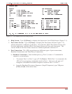
3.2. The Port Status Screen (Model APS-16; Defaults Shown)
..................
3-4
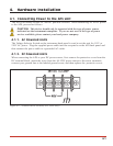
4.1. Terminal Block Assembly (DC Units Only)
..........................
4-1
4.2. APS Application Example (Model APS-16 Shown)
.....................
4-5
5.1. Port Configuration Menu (Port 2 Shown)
...........................
5-5
5.2. Port Parameters Menu (Modem Mode)
.............................
5-7
5.3. The Copy Port Parameters Menu
................................
5-9
6.1. The Port Status Screen (Supervisor Mode, APS-16 Shown)
.................
6-1
6.2. The Port Diagnostics Screen (APS-16 Shown)
........................
6-2
6.3. The Port Parameters Screen
...................................
6-4
A.1. RS232 Port Interface
.....................................
Apx-1
iv