


2.2. Back Panel
¬
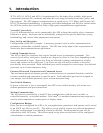
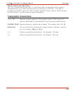
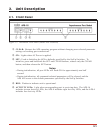
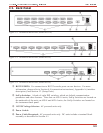
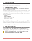
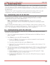
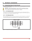
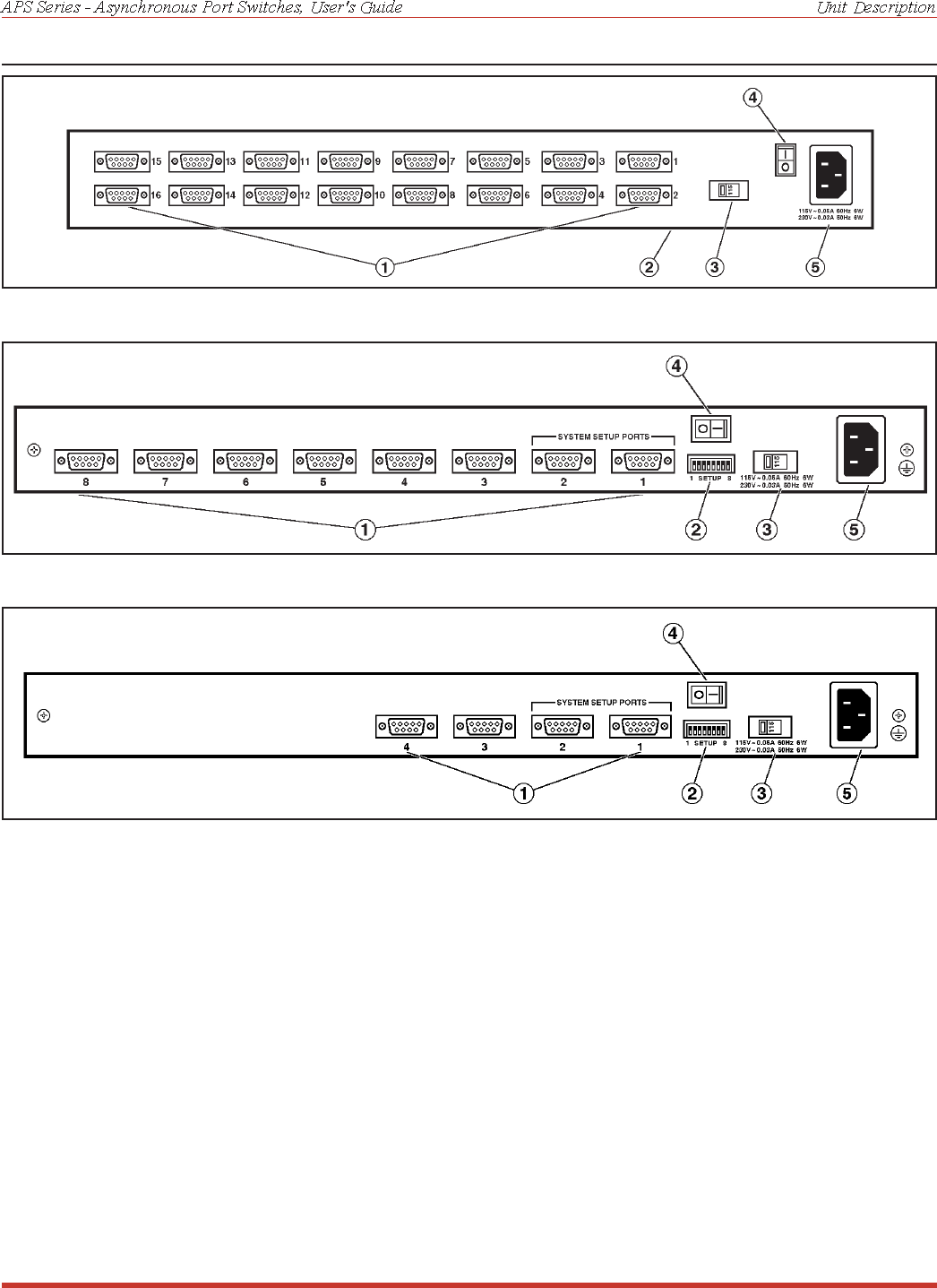
RS232 PORTS: For connection to RS232 console ports on user devices. For more
information, please refer to Section 4.4 (connection instructions), Appendix A (interface
description), and Section 5.2 (Setup Ports).
SetUp Switches: A bank of eight DIP switches, which set default communication
parameters and other features. Note that on APS-16 units, SetUp Switches are located on
the underside of the unit; on APS-8 and APS-4 units, the SetUp Switches are located on
the instrument back panel.
® 115/230 Voltage Selector: AC powered units only.
¯ Power Switch
° Power Cable Receptacle AC powered units only. DC units include a terminal block
assembly as described in Section 4.1.
2-2
Figure 2.2: Instrument Back Panel (Model APS-16)
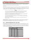
Figure 2.3: Instrument Back Panel (Model APS-8)
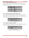
Figure 2.4: Instrument Back Panel (Model APS-4)