MA7200 PLUS Inverter 1 to 2 HP PID Fan and Pump Quick Start Manual
__________________________________________________________________
________________________________________________________________
TECO – Westinghouse Motor Company
10
PRGM
DRIVE
DSPL
EDIT
ENTER
Sn – 01 -
key twice
Inverter Capacity
Flashing
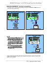
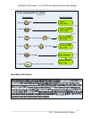
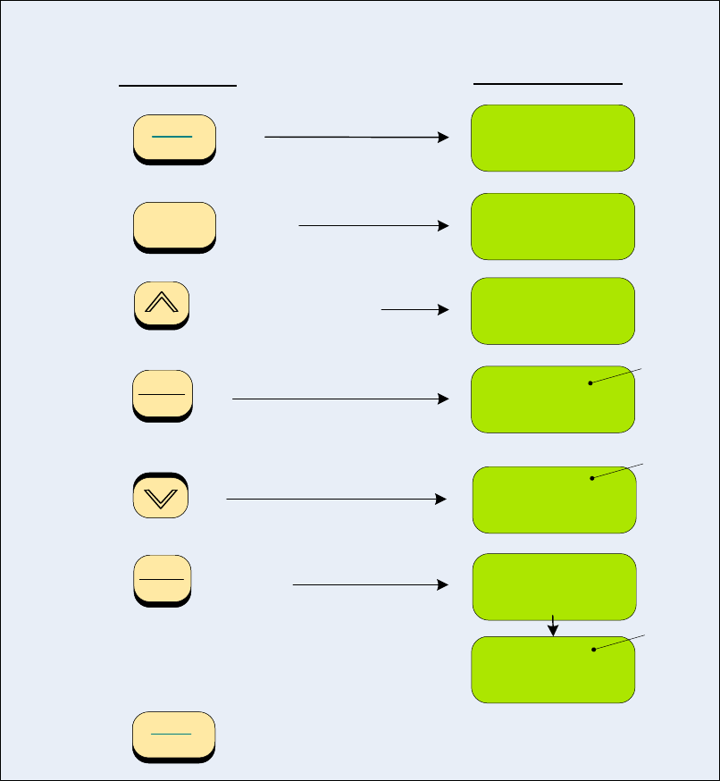
To set the parameter Sn-24 = 0
Keypad Steps
Resulting Display
1 - Press the
2 - Press the
3 - Press the
key until display shows
4 - Press the key
(VIN, 0 – 10 VDC)
key
An – 01 -
Freq. Cmd. 1
Sn – 24
Sn – 24 = 1
CMD. AIN
EDIT
ENTER
key to save.
5 - Press the
key
6 - Press the
Entry Accepted
2 Seconds
PRGM
DRIVE
7 - Press the
key to return to the main display.
Flashing
Sn – 24 = 0
CMD. VIN
Flashing
Sn – 24 = 0
External Input
CMD. VIN
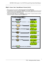
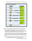
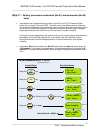
Step 9 – Select Feedback Engineering Units (P1-01) and Scaling (P1-02)
• Initially the display will read output frequency in (Hz) as the factory default and is set by
parameter (Cn-28=0). If (Cn-28) is changed to (=1), then the display will read out in (%). The
setting of (Cn-28) is only valid if (P1-01=0), which is the factory default. Other engineering units
may be selected by parameter setting (P1-01) as described on the following page.
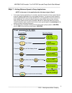
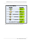
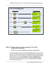
• In this step, the feedback engineering units that the system is controlling such as CPM in fan
applications or PSI in the case of pumps can be selected by parameter (P1-01). (See Appendix
A for additional selections). The maximum value that the engineering units will be in any given
application is set by parameter (P1-02). These selections will now be displayed on the digital
operator.
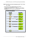
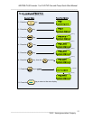
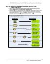
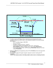
Example: A pump application that has a feeedback transducer with a maximum value of
200 PSI i.e 200 PSI = 20mA or 10 Vdc, can be set as shown next.


