


A-2
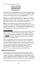
RS-422 Termination Jumpers
Refer to the circuit board diagram on page A-1 for details.
The Base can be jumpered to be 422 terminated or not terminated. By
default, all Base stations are shipped as terminated. Use the following
guidelines to change the termination for your system:
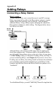
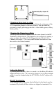
• If the Base has multiple strings of relays radiating from it, the
Base would not be terminated.
• If the Base is first in a string, (not in the middle or end of a
string), set the 422 jumpers to Base w/RS-422 termination.
• The last Relay in each string should have its jumpers set as a
Relay w/RS-422 termination.
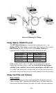
Channel Changes
To determine the current channel of a Base Station , power up the Base
and watch the LED light on the front of the unit. On power UP, a Base
LED will blink "channel +3" times. For example, a unit that blinks 5
times on power up is operating on channel 2. Channel 0 blinks 3 times,
channel 5 blinks 8 times.
A Base Station jumpered to operate as a Base blinks green; a Base
Station jumpered to operate as a Relay blinks yellow.
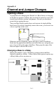
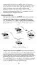
Changing the Channel on a Base/Relay
The Base Station and its related Relays must have their frequencies set
to the same channel as the R/F Terminals in their network. The channel
is set on a Base /Relay by turning a rotary switch to the setting 0-F (10
different channels to choose from). Use a very small flat head
screwdriver to turn the switch to the desired number. See the circuit
board diagram on page A-1 for location of the rotary switch
Setting the Relay ID
Each Relay must also have a unique ID, which is set by the RF
Terminal Serial Configuration Utility.