


B-2
running from the unlabeled port on the Base station. See the section
below for cabling requirements and pin-outs. It is very important to follow
the pin-out directions carefully and to use the suggested cable type. The
majority of problems we see are the result of incorrect wiring.
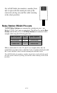
Each Relay requires it’s own power supply. There is no serial
parameter setup required on a Relay as it is transmitting only to the
Base station and not directly to a serial port.
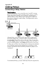
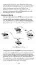
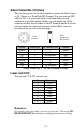
Routing the Wiring
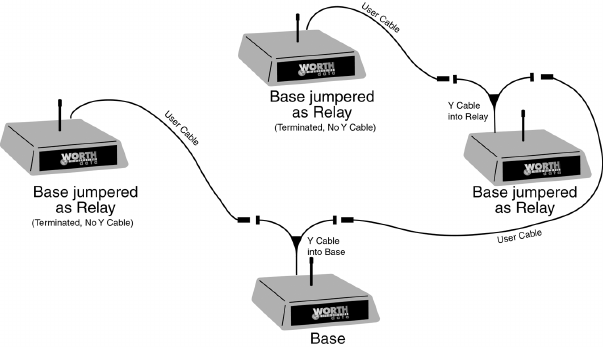
The below diagram illustrates the RIGHT way to route your wiring
and which units should be terminated. Notice this is the classical bus
interface where the Base and Relays are connected to a “one-cable
bus”. The bottom of the Y-Cables is connected into the unterminated
base or relay(s). Notices that the two end units are terminated; the units
in the middle are unterminated, including the Base in this example.
Correct Routing for Wiring
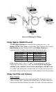
The next diagram illustrates the WRONG way to route your wiring and
use the Y-cables. Sometimes people try to route everything through a panel
or wiring closet – this will not work properly; it will generate excessive
data noise and drag down the responsiveness of the Base and application.
(With too much noise, the Base will stop working and issue a “Base Station
Reinitalized” message to the terminals. If used, such a radial interface as
below might appear to work most of the time, but it would be very sluggish
and crash several times per day. Terminating or not terminating will be of
no help. Do Not cable as shown on the following page: