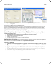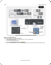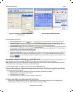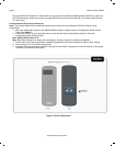
Page 2 RS2321X8 Serial Router
SPECIFICATIONS:
• Power Input: 12VDC @150mA (2.1mm Coaxial Jack)
• RS232 Source Input Connection: Male DB9 Connector
• RS422 Source Input Connection: Female RJ45 Connector
• RS232 Output Connection: 4-Female DB9 Connectors
o Maximum Wire Distance from Router to Device: 100ft (distance may vary depending upon device and
wiring configuration)
• RS422 Output Connection: 4-Female RJ45 Connectors:
o Maximum Wire Distance from Router to Device: 4000ft (distance may vary depending upon device and
wiring configuration)
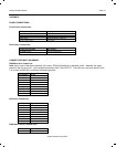
• IR Control Input Connection: 4-Screw Terminal (12VDC In/Out, GND, STATUS, IR INput)
• IR Control Default Group Code: 90
• Baud Rates Supported for Output Port Switching (Note: All Baud Rates Supported for RS232 Pass Thru): 300,
600, 1.2k, 2.4k,4.8k, 9.6k, 19.2k, 38.4k, 56kbps) Note: MRC88 uses 38.4kbps; SmartPad LCD™ uses 56kbps.
• Dimensions: 9.6” L x 3.0” W x 0.75” H (244mm L x 77mm W x 19mm H)
INSTALLATION
POWER WIRING:
1. Connect a 12VDC power supply (Xantech Model 781RG or 782-00 ) to the 2.1mm coaxial power input jack
(labeled 12VDC).
2. Plug the AC Adaptor into an un-switched AC Outlet.
Note: The Screw Terminal connection may also be used to hard-wire the power supply to the RS2321X8 Serial
Router. Use 18AWG to 24AWG 2-conductor wire connected to the 12VDC and GND screw terminals.
OUTPUT SERIAL WIRING:
Serial RS422 Output Wiring (Ports 1 thru 4):
Note: Use Xantech Model RS422232 (RS422 to RS232 Converter Module) to convert the RS422 output back to
standard RS232 Serial configuration directly at the Remote Serial Device to be controlled. RS422232 Module may be
placed up to 4000ft. from the RS2321X8 Router Port.
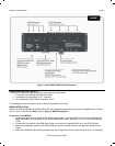
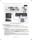
1. Connect one end of an RJ45 terminated CAT5 cable to the appropriate Serial Port (Labeled Port 1 thru 4) of the
RS2321X8 Router.
2. Connect the other end of this CAT5 cable to the connector labeled SERIAL on the RS422232 converter located at
the remote location within close proximity of the Serial device to be controlled.
3. Connect a Female DB9 terminated serial cable to the RS422232 connector labeled RS232.
4. Connect the other end of this cable to the Serial device being communicated to. (See Note
1
below)
5. Connect a 781RG 12VDC power supply to the 2.1mm Coaxial Power jack on the RS422232 Converter.
Note
1
: Some Serial devices require the use of a ‘Null Modem’ cable or connector for proper communication. You will
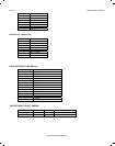
need to consult the products instruction manual to see if this is required. Refer to Table 1A for Xantech Model
RS422232 Pin Out information.
Serial DB9 Output Wiring (Ports 5 thru 8):
1. Connect a Female DB9 terminated serial cable to the appropriate Serial Ports (labeled Port 5 thru 8) of the
RS2321X8 Serial Router.
2. Connect the other end of this cable to the Serial device being communicated to. (See Note
1
above)
© 2005 Xantech Corporation


