Section 2. Installation and Configuration
Configuring
14 Operating Manual for APG for XT/HPD Series Power Supply
Configuring
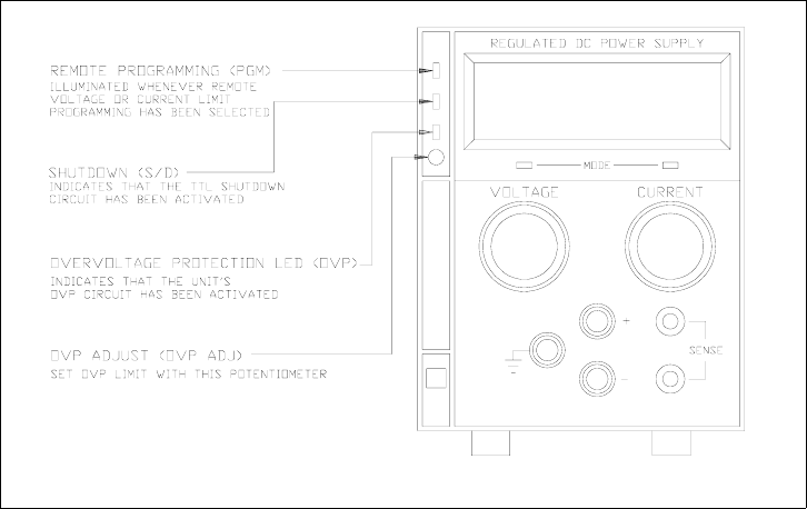
Configure and adjust the analog programming interface installed in your XT or HPD
DC power supply as indicated in this section. The front panel LEDs indicate when
V or I programming is selected (PGM), when TTL shutdown has occurred (S/D), and
when the supply exceeds the voltage trip point OVP). You can adjust the OVP right
at the front panel. You will find the main programming option switch and connector
on the unit's rear panel, see Figure 2.2.
Front panel
Figure 2.1 XT/HPD Front Panel with APG Interface Installed
(typical configuration)


