Section 2. Installation and Configuration
Rear Panel J5 Connector
16 Operating Manual for APG for XT/HPD Series Power Supply
Rear Panel J5 Connector
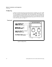
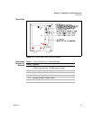
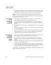
Make analog interface connections via the rear panel 25-pin female DSUB connector
designated J5. To provide the lowest noise performance, we recommend you use
shielded-twisted pair wiring for making connections from external circuits to the J5
connector. Use the shortest leads possible. Ground the shield to pin 6 (auxiliary
ground) on the J5 connector or to the chassis via one of the J5 connector screws.
Note:In order to maintain isolation of power supply output, any programming
source must also be an isolated source.
J5 Connector
Pin
Assignments
Table 2.2 J5 Connector Pin Assignments
* Negative Logic: LOW = ACTIVE
Pin Function
1 Over Voltage Protection Flag
2 TTL Shutdown Return
3 Not Used
4 Program Return
5 Program Return
6 Auxiliary Ground
7 Remote Voltage Program Select*
8 Remote Current Program Select*
9 Voltage/Current Limit Mode Indicator
10 + OUT
11 + OUT
12 RTN
13 RTN
14 Not Used
15 TTL Shutdown
16 Current Limit Program
17 Voltage Program
18 Current Readback
19 Voltage Readback
20 +10 V Reference OUT (10 mA max.)
21 Output Fail Flag*
22 + SNS
23 + OUT
24 RTN
25 RTN SNS


