


Section 3. Operation
Remote Programming
Release 1.0 21
Programming
Output
Current with
a 0-10k
Resistance
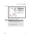
1. Select remote current programming by external resistance by moving the rear
panel switch S1-3 (remote current program select) to the ON (closed) position.
Or, connect J5 pin 8 (remote current program select) to J5 pin 6 (auxiliary
ground). As these two control functions are wired in parallel, they function as a
logic OR.
2. Set rear panel switch S1-2 (resistive current program select) to the ON (closed)
position.
3. Connect a variable resistance between J5 pin 16 and either pin 4 or pin 5
(program return).
4. Adjust the resistance from 0-10kΩ to vary the power supply current limit from
0-100% of rated output. You may set the power supply's output voltage using
another source or the front panel voltage control.
Programming
with a Fixed
+10V
Reference
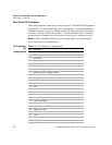
The APG Interface J5 connector provides a +10 V reference output at pin 20 for
applications which require a fixed output voltage and/or current limit. The current
from this output must be less than 10 mA.
To program output voltage:
1. Connect resistor A between J5 connector pin 20 (+10 V reference out) and pin
17 (voltage program).
2. Connect resistor B between pin 17 (voltage program) and either pin 4 or 5
(program return).
To program current limit, follow the procedure used to set up for programming
output voltage, substituting pin 16 (current program) for pin 17.
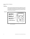
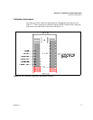
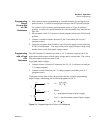
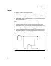
Figure 3.1 Programming with a Fixed +10V Reference
V
OMAX
R
B
V
o
= --------------
R
A
+ R
B
Where:
V
o
= programmed output of power supply
V
oMAX
= rated maximum output of power supply
R
A
+ R
B
> 1k
J5-20
J5-17
J5-4
+10 V
Vpgm
R
A
R
B