Installation
18 975-0004-01-02 Rev D
Configuring the C-Series Controller
Before making any wiring connections to the C-Series
controller, it must be configured for the desired mode of
operation. The following sections describe the how to
configure the unit for the desired application and function.
Jumper Settings
Three sets of jumpers are located on the right side of the
controller’s circuit board. These jumpers control
equalization, low voltage reconnect, battery voltage, and
operating modes. They must be installed correctly for the unit
to operate to its maximum potential.
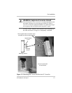
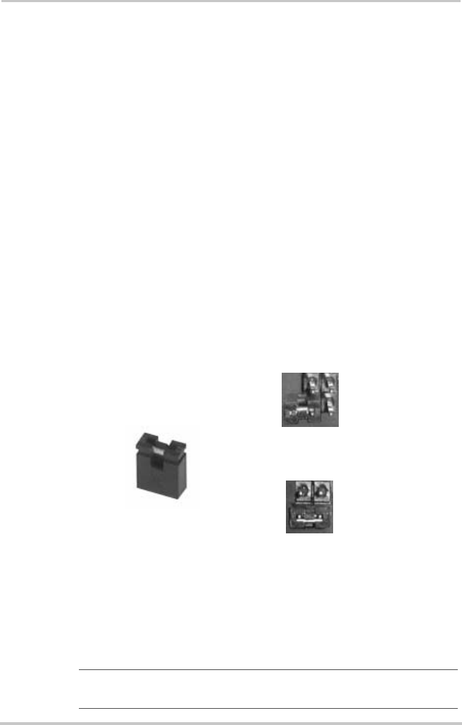
To enable a selection, carefully slide the jumper over the top
of both pins. This is called installing the jumper.
To disable a selection, carefully slide the jumper over only
one of the pins. This is called removing the jumper.
The factory default settings are shown in Table 2-1, “Factory
Default Settings for C-Series Controllers” on page 19.
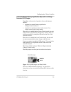
Figure 2-4
Jumper Positions
Important:
Use extreme caution when installing and removing
jumpers so as not to bend the pins.
Jumper
Jumper Installed
(Jumper is on both pins)
Jumper Removed
(Jumper is only on one pin)


