Wiring - Specific
152315 Rev C 3–15
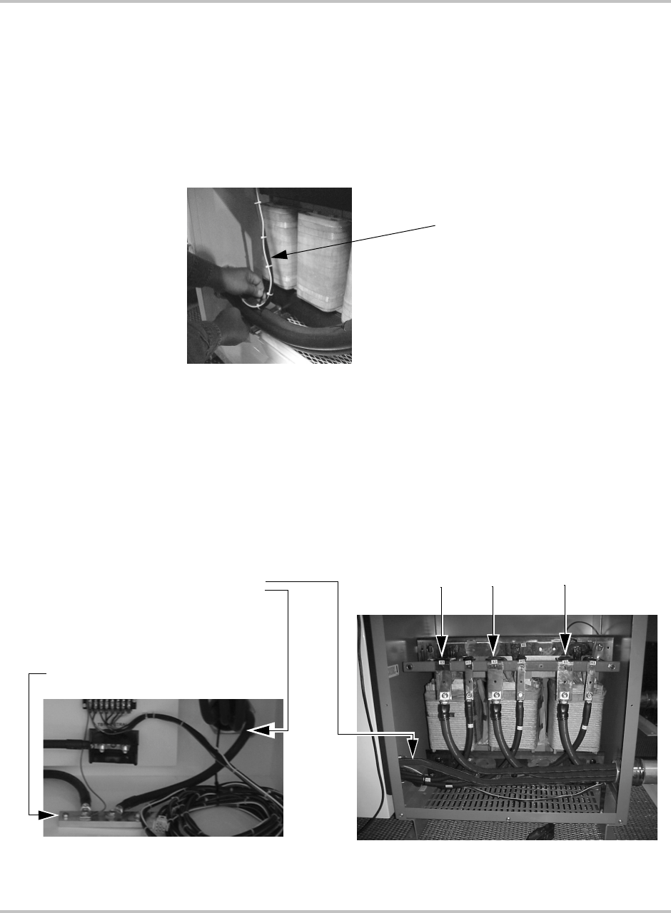
3. In addition to the power conductors, route the AC Sense Harness assembly
(Xantrex P/N 1-152403-01) between the main inverter to the AC
interface/transformer assembly. Prior to completing the installation of the AC
Sense Harness, secure the harness to the AC power conductors with nylon
tie-wraps so it does not touch the surfaces of the L1 inductor. Failure to secure
the AC Sense Harness away from these surfaces may cause deformation of
the harness insulation and possibly damage due to the excessive heat
generated by the L1 inductor
.
4. Connect the AC power conductors in the Transformer Enclosure at the T6-X1
(A phase), T6-X2 (B phase), and T6-X3 (C phase) bus bars using
3/8-16" hardware. Connect the ground conductor in the AC
Interface/Transformer Enclosure at TB2. Cables to these terminals must use a
crimp-on type ring terminal or compression-type lug. Tighten these
connections to a torque value of 420 in-lbs (47.5 Nm).
Figure 3-13
Tie-wraps on the AC Sense Harness
Prior to completing the installation
of the AC Sense Harness, secure
the harness to the AC power
conductors with nylon tie-wraps.
Figure 3-14
AC Terminal Connections in the AC Interface/Transformer Enclosure
Transformer Enclosure
AC Interface Enclosure
TB2 Ground Bar
Ground Cable from
Main Inverter
Enclosure
T6-X1
T6-X3
T6-X2
