


Wiring - Specific
152315 Rev C 3–19
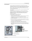
PV Array Connections
To make the connections from the PV Array/combiner to DC Interface
enclosure:
1. Remove the door clamps and open the door to the DC Interface Enclosure.
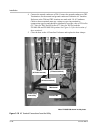
2. Route the PV Array cables conductors POSitive (PV+), NEGative (PV-), and
PV GND through the conduit to the DC Interface Enclosure, entering on the
underside.
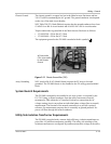
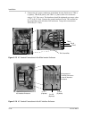
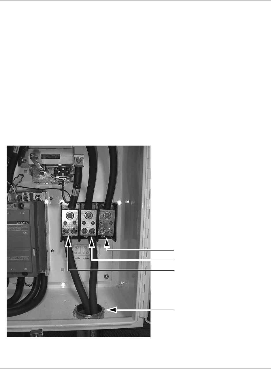
3. The DC power conductor terminations are made at the TB3-1 (POS/DC+),
and TB3-2 (NEG/DC-) and TB3-3 (PV Gnd) locations. See Figure 3-19.
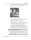
4. Terminations for the POSitive, NEGative, and GND conductors within the
DC Interface enclosure at the TB3 locations are made with box connector
using a 7/16" Hex Allen screw. The hardware should be tightened to a torque
value of 500 in-lbs. (56.5 Nm) for both the PV100S-480 and PV100S-208
systems.
5. Close the door to the DC Interface Enclosure and replace the door clamps.
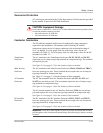
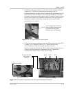
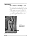
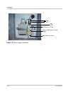
Figure 3-19
PV Array Cable Routing and Terminations
PV POSitive Cable (TB3-1)
PV NEGative Cable (TB3-2)
Conduit entry from PV Array
GrouND (TB3-3)