Installation and Configuration
Basic Setup Procedure
20 Operating Manual for RS-232 for XT/HPD Series Power Supply
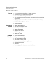
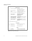
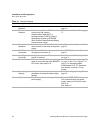
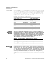
Table 2.1 Setup Procedure
Step # Description Action Reference
1 Baud Rate
Selection
Select transmission speed See
“Baud Rate Selection” on
page 21
.
2 Flow Control
Selection
Set flow control ON or OFF. If flow
control is set ON, choose
software-based XON/XOFF or
hardware-based CTS/RTS (Clear to
Send/Ready to Send) or DTR/DSR
(Data Terminal Ready/Data Set Ready)
communication control.
“Flow Control Selection” on page
22
.
3 Remote/Local
Operation
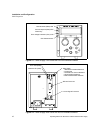
Use the rear panel REM/LOC switch to
select remote or local state of the power
supply.
See
“Remote/Local Operation” on
page 25
.
4 RS-232
Connection
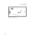
Connect the RS-232 cable assembly to
the supply at connector J4.
See
“RS-232 Connection” on
page 27
5 User Signal
Connector
Configure and use the J7 connector
signals, if required.
See “Connector J7 User Signals”
on page 31
.
6 Power ON Power on the unit. Before proceeding,
check to ensure that the green REMOTE
LED on the front panel is on.
See
“User Options and Settings”
on page 29 and “User Signals” on
page 31
for information about
Local/Remote OVP, TTL Shutdown,
and auxiliary connector J7 user
signals.
7 Power Supply
Settings
Configure the controller’s operating
parameters to match the power supply
settings.
See
“Power Supply Settings” on
page 28.
8 Test Test the link by communicating with the
power supply.
Example: VSET2;ISET1
This command string sets power
supply voltage to 2V and its current
limit to 1A.
See Section 3.


