Installation and Configuration
Communications
Release 1.1 23
Hardware
Flow Control
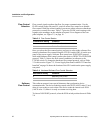
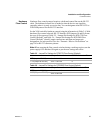
Hardware flow control protocol requires a dedicated control line on the RS-232
cable. The dedicated control line is needed so that the device can signal the
controller when it is ready to receive data. You can designate either RTS/CTS or
DTR/DSR protocol for the RS-232 interface.
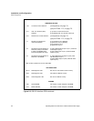
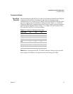
Set the XON switch for hardware control using the information in Table 2.4. With
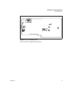
hardware flow control selected, RS-232 Interface PCB jumpers J8 and J9 dictate
the type of flow protocol. Table 2.5, “Jumper/Pin Settings for RTS/CTS Flow
Control (Default)” and Table 2.6, “Jumper/Pin Settings for DTR/DSR Flow
Control (Default)” identify jumper connections and input and output pin
designations for each protocol. See also “Transmit / Receive Pin Selection” on
page 24 for RS-232 connector pinouts.
Note:When resetting the flow control switches during a working session, turn the
power supply OFF and then ON again to put the new settings into effect.
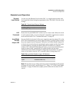
Table 2.5 Jumper/Pin Settings for RTS/CTS Flow Control (Default)
Table 2.6 Jumper/Pin Settings for DTR/DSR Flow Control (Default)
Jumper Connections RS-232 Connector Pin
RTS (Input to RS-232)
J8 to 2-4 and 3-5
7
CTS (Output to RS-232)
J9 to 1-3 and 4-6
8
Jumper Connections RS-232 Connector Pin
DTR (Input to RS-232)
J8 to 2-4 and 1-3
4
DSR (Output to RS-232)
J9 to 3-5 and 4-6
6


