Operation
Command Reference
46 Operating Manual for RS-232 for XT/HPD Series Power Supply
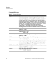
Command Description
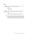
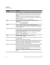
OUT <1/ON>,<0/OFF> Enables or disables the supply’s voltage/current output. The supply will
continue to accept new commands while the output is disabled but these
will not be implemented until OUT ON or OUT 1 is received. OUT ON is the
default setting. When you start the supply in remote mode, the output is
enabled.
OUT OFF (or OUT 0) also sets the isolation signal on the rear panel J7
connector, line 3. You can use the to trip external relays to isolate the power
supply from the load.
Initial value: OUT ON (or OUT 1) for output enabled
OUT? Returns the present enabled/disabled status of the supply’s output
voltage/current.
Response: OUT 1 output enabled or
OUT 0 output disabled
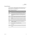
OVCAL Causes the master controller to perform automatic calibration of the
supply’s over voltage protection circuitry. Set CMODE ON before using this
command. Ensure jumper J95 on the RS-232 Interface PCB is connected
for remote operation.
OVSET <voltage> Sets the supply’s over voltage protection trip point in volts (default) or in
millivolts. If the trip point is exceeded, or if the trip point value is lower than
the present output voltage setting, the supply will ignore the command, turn
on the ERR LED, and set the ERR bit in the accumulated status register.
Reset with the RST command.
Range: 0 to 110% of model maximum output voltage (VMAX)
Initial value: 110% of model VMAX
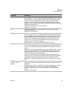
OVSET? Returns the supply’s present over voltage protection limit.
Response: OVSET <voltage>
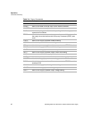
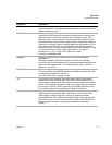
ROM? Returns the version number of the master and slave EPROMs located on
the interface PCB.
Response: ROM M:<version> S:<version>
RST Resets the supply to present voltage and current settings if the output is
disabled by over voltage or foldback protection. Output values may be
changed via VSET, ISET, and OVSET while the unit is disabled, but those
values will not take effect until RST is applied.
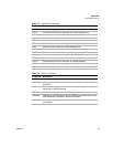
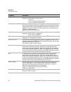
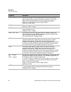
STS? Returns the supply’s present status register. Status conditions are stored in
the status register. Each bit represents a separate condition. When the
condition is true, the corresponding bit is 1 (true). Bits remain set in the
status register as long as the condition is true. See
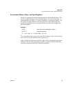
“Accumulated Status,
Status, and Fault Registers” on page 49
.
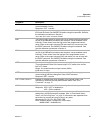
Response: STS <status mask> where status mask is the decimal equivalent
of the total bit weights for the operating conditions as listed in the status
register.


