


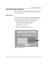

Operational Status Indicators
976-0043-01-02 8–5
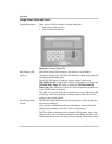
AC Input Status (Green)
Status LEDs There are two green LEDs to indicate AC status conditions.
• AC1 LED (grid)
• AC2 LED (generator)
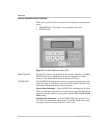
AC1 (Grid)
LED
The AC1 LED indicates power has been applied to the inverter’s AC1
(grid) input terminals. When AC is initially detected, the LED blinks
slowly (once per second). If the AC source is within the user’s input
settings, the inverter will connect to the source and the LED will be ON
solid. If the AC source falls out of tolerance, the LED will start to blink
and the AC input source will be disconnected. If using BX Modeor the
Grid Usage Timer, this LED will continue to blink even if the source is
within tolerance.
AC2 (Generator)
LED
The AC2 LED indicates power has been applied to the inverter’s AC2
(generator) input terminals. When AC is initially detected, the LED blinks
slowly (once per second). If the AC source is within the user’s input
settings, the inverter will connect to the source and the LED will be ON
solid. If the AC source falls out of tolerance, the LED will start to blank
and the AC input source will be dropped.
Bypass Mode If the inverter is being used in Bypass Mode, the AC1 or AC2 LEDs,
along with the STATUS LED will illuminate solidly, depending on which
AC input source is selected. However, the inverter will not monitor the
AC inputs for power quality.
Figure 8-3
AC Status LEDs