


Calibration
Remote Interface Calibration Procedure
188 Operating Manual for XDC Series Power Supply
3. Enter current data
Enter the current read from the external DVM via the shunt.
CAL:OUTP:CURR:DATA <current>
4. Maximum calibration level
Set the output current to 90% by sending the command:
CAL:OUTP:CURR:LEV MAX
5. Enter current data
Enter the current read from the shunt via the external DVM.
CAL:OUTP:CURR:DATA <current>
6. Power supply calculates and stores calibration constants.
Analog
Programming
Interface 0-5V
Range
To set up to calibrate the analog programming interface, you will need a DC power
source capable of outputting 0 to 5V and a DVM.
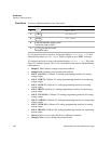
Table 4.2 “Analog Programming Pins”
Analog Programming Interface Voltage Programming Calibration
1. Connect the power source across the voltage programming lines, Pins B3 and
B1(GND). Attach a DVM across the voltage programming lines as well.
2. Minimum calibration level
Set the input to the programming lines to approximately 0.5V (10% of full
scale).
Set the power supply to receive 5V analog voltage programming calibration data
with the command:
CAL:ANAL:5V:PROG:VOLT:LEV MIN
3. Enter voltage data
Enter the voltage at the voltage programming lines, read from the external DVM.
CAL:ANAL:5V:PROG:VOLT:DATA <voltage>
4. Maximum calibration level
Set the input to the programming lines to approximately 4.5V (90% of full
scale).
Set the power supply to receive 5V analog voltage programming calibration data
with the command:
CAL:ANAL:5V:PROG:VOLT:LEV MAX