


PLB PCI Full Bridge (v1.00a)
DS508 March 21, 2006 www.xilinx.com 51
Product Specification
E
AR
L
Y
ACCESS
Design Debug
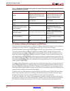
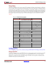
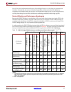
The OBP PCI Bridge has a test vector output (PCI_monitor) to facilitate system debug (i.e., adding an
ILA to a system). The test vector allows monitoring the PCI bus and is the output of IO-buffers that are
instantiated in the LogiCORE v3.0 PCI core. PCLK, RCLK, and Bus2PCI_INTR are not included in the
test vector because these signals do not have io-buffers instantiated in the Bridge and are accessible to
use directly at the core top-level or above. If the port is not connected in the EDK tool top-level mhs-file,
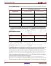
the wrapper simply leaves this port open. PCI Bus monitoring test vector bit definition is listed in
Table 24.
.
Table 24: PCI Bus Monitoring Signals
Bit Index Signal Name Instantiated IO-Buffer
PCI Transaction Control Signals
0 FRAME_N Ye s
1 DEVSEL_N Ye s
2 TRDY_N Ye s
3 IRDY_N Ye s
4 STOP_N Yes
5 IDSEL Ye s
PCI Interrupt Signals
6 INTR_A Optional
PCI Error Signals
7 PERR_N Ye s
8 SERR_N Ye s
PCI Arbitration Signals
9 REQ_N Optional
10 GNT_N No
PCI Address, Data Path, and Command Signals
11 PAR Ye s
12-43 AD[31:0] Ye s
44-47 CBE[3:0] Ye s
Design Verification
The PLB PCI Bridge design will be verified according to IPSPEC000 PLB PCI Bridge Verification Plan.
Design Contraints
The OPB PCI Bridge uses the LogiCORE PCI64 v3.0 core that requires specific constraints to meet PCI
specifications. UCF-files with the constraints for the LogiCORE PCI64 v3.0 core in many different
packages are available from the LogiCORE Lounge. The PCI64 v3.0 core specific constraints can be
included in the top-level ucf-file by the user.