


15
Connection
7
English
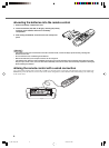
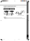
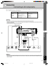
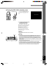
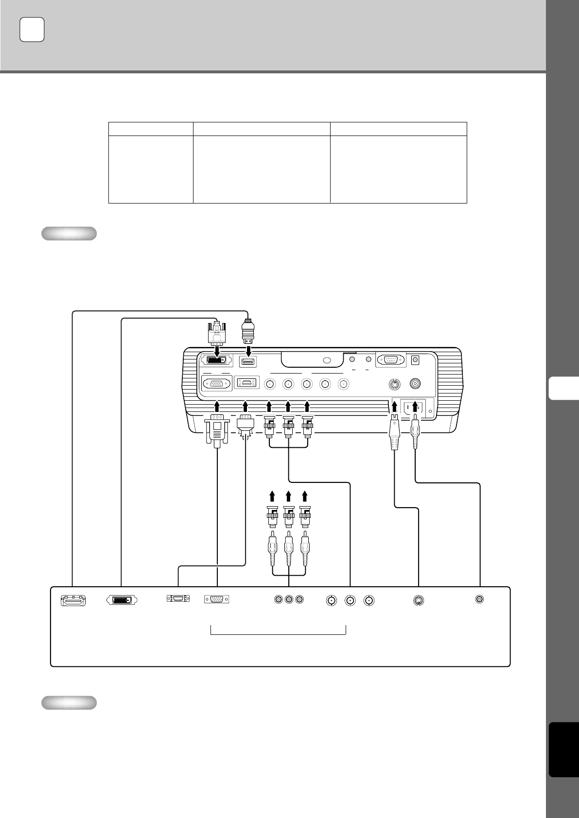
Connecting to AV components
This unit is equipped with 7 types of video input jacks for AV components. Follow the diagram to connect AV components to this unit, taking
care to use cables and adapters that match the input jacks.
Warning
• Be sure to turn off the power of this unit and the source component before attempting connection.
• Connection methods and jack names may differ depending on the component you are attempting to connect. Refer to the owner’s
manual for the component.
• Insert all plugs firmly to avoid noise or other problems.
Memo
• Be sure to connect Y/PB/PR and Y/CB/CR to the jacks with the correct signals when connecting AV components to INPUT A. Refer to
the owner’s manual of the source component for more information. You may need to make connections to HD/SYNC and VD for
RGB video signals.
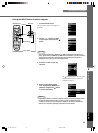
D connector
cable
D-sub
monitor
cable
BNC cable for
component connection
Pin/BNC
adapters
Pin cable
Video pin cable
S-Video cable
D1—4
output
connectors
Pin jacksD-sub
Component/RGB video output connectors
Image output from AV components
BNC jacks S-Video output
jack
Video output
jack
HDMI cable (digital)
HDMI
output
connector
7 Connection
DVI cable (digital)
DVI output
connector
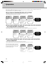
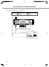
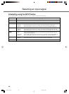
Input
VIDEO
S VIDEO
INPUT A
INPUT B
D4 VIDEO
HDMI
DVI
Signal type
Composite video
S-Video
Component video/RGB video
Component video/RGB video
Component video
Component video/RGB video (digital)
RGB video (digital)
Connector type
Pin jack
Mini DIN connector
BNC connector x 3-5
D-sub 15 pin
D connector
HDMI connector
DVI connector
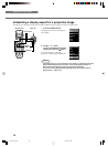
HDMI
G/Y B/P
B
/C
B
R/P
R
/C
R
INPUT A
HD/SYNC
VD
OUT IN
REMOTE
TRIGGER OUT
S VIDEO VIDEO
INPUT B
RGB/YP
B
P
R
/YC
B
C
R
RS-232C
D4 VIDEO
DVI
G
/
YR
/
P
R
/
C
R
B
/
P
B
/
C
B
11_DPX-1300_E.p65 9/20/05, 5:07 PM15