


VES-1000 Series Ethernet Switch
3-8 Installation Scenarios
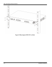
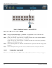
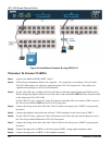
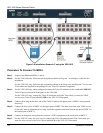
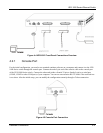
Figure 3-8 Installation Scenario C using the VES-1012
Procedure To Connect To MDFs
Step 1. Acquire two additional MDFs (3 and 4).
Step 2. For the VES-1008 only, follow the pin assignments shown in Diagram 5 to configure a cable for this
installation.
For the VES-1012 only, follow the pin assignments shown in the Diagram 6 and Diagram 7 to wire two
Telco cables (not supplied in the package) to two Telco-50 connectors (supplied).
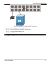
Step 3. For the VES-1008 only, when configured, connect the Telco-50 connector to the combined USER/CO
Telco-50 port located on the front panel of the VES-1008.
For the VES-1012 only, connect the Telco-50 connector end of the Telco cable you want for VDSL
service to the Telco-50 port labeled USER on the VES-1012 front panel.
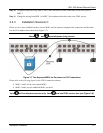
Step 4. Connect the wiring on the other side of the Telco-50 cable to the upper ports of MDF 3 using a punch-
down tool.
Step 5. Connect the lower ports of MDF 3 to the upper ports of MDF 2 for those users that want VDSL service.
(Users who want to telephone service only, retain the original connection from the top port of MDF 2 to
the bottom port of MDF 1.)
Step 6. Connect the telephone wiring from the end-user’s VDSL equipment to the lower ports of MDF 2.
Step 7. For the VES-1012 only, for voice service, connect the Telco-50 connector end of the Telco cable you
want for voice service to the Telco-50 port labeled CO on the VES-1012 front panel.