


VES-1000 Series Ethernet Switch
2 Index
L
lightening.................................................................. H
M
M3 flat head screws................................. 2-1, 2-3, 2-5
M5 flat head screws..........................2-1, 2-2, 2-3, 2-5
MDF (Main Distribution Frame).................... 3-2, 3-3
MDF blocks............................................................3-3
MDF Description....................................................3-3
Mounting Brackets ......................................... 2-2, 2-5
MTU.......................................................................1-1
O
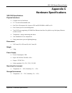
Operating Environment............................................ G
P
P841........................................................................3-1
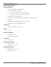
Physical Interfaces............................................... G, H
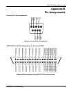
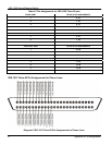
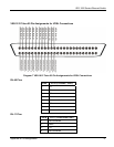
Pin Assignments ..................................3-4, 3-6, 6-2, C
Console Port ......................................................... C
Phone Lines.......................................................... D
RJ-11 .....................................................................E
RJ-45 .....................................................................E
Telco-50 Phone Lines........................................... D
Telco-50 VDSL.....................................................E
VDSL Connections................................................E
port trunking................................................... 4-4, 6-3
Power Consumption ................................................. H
Power Switch..........................................................5-1
Preface......................................................................ix
Punch Down tool....................................................3-3
PWR ............................................................... 5-2, 6-1
R
Rack Mounting
Precautions ................................................. 2-1, 2-5
Rack-mounted ........................................................2-1
Rack-mounted VES-1012 Installation....................2-4
Rear Panel Connections
Connections........................................................4-2
Power Cord.........................................................4-1
Rear Panel ..........................................................4-1
Related Documentation............................................ix
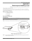
Removing and Installing A Fuse.............................. A
Removing Fuses....................................................... A
Before you Begin ................................................. A
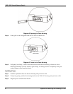
Opening the Fuse Housing....................................B
Repair .......................................................................iii
Replacement.............................................................iii
Residential Building Application...........................1-1
Return Material Authorization number (RMA.........iii
RJ-11 connectors.............................................3-1, 3-3
RJ-45 ..................................................... 4-4, 6-3, E, H
RS-232...............................................................4-3, H
run a self-test..........................................................6-1
S
Scenario A..............................................................3-3
Scenario B ..............................................................3-4
Scenario C ..............................................................3-7
Scenarios ................................................................3-3
Screws .............................................................2-2, 2-5
Self-diagnostic........................................................5-2
sensors...................................................................... H
Service......................................................................iii
Services ....................................................................iv
Speed......................................................................6-3
Splitters ..................................................................3-1
stack........................................................................4-4
Storage Environment................................................ G
Straight-through Category 5 UTP (Unshielded
Twisted Pair) Cable.....................................4-4, 6-3
Syntax Conventions..................................................ix
SYS ......................................................... 5-1, 5-2, 6-1
SYS LED................................................................6-1
SYS LED does not Turn On...................................6-1
T
Telco-50 .............. 3-3, 3-4, 3-6, 3-8, 3-9, 6-2, D, E, H
Telnet......................................................................4-3
Temperature........................................................ G, H
Testing In-house Wiring..................................6-3, 6-4
Trademarks................................................................ii