


VES-1000 Series Ethernet Switch
6-2 Hardware Troubleshooting
The ALM LED Is On
The ALM (alarm) lights when the VES-1000 Series switch is overheated and/or the fans are not working properly
(VES-1012 only) and/or voltage readings are outside the tolerance levels. The VES-1000 Series switch may
become damaged if the ALM LED remains on.
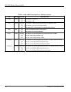
Table 6-3 ALM LED Troubleshooting
STEP CORRECTIVE ACTION
1 Go to SMT Menu 24.12 - Hardware Monitor to verify the cause of the alarm. See step 2 if the unit is
overheated, step 3 if the problem is with the fans and step 4 if the voltages are out of the allowed ranges.
2 If the unit is overheated, turn it off and wait for it to cool down. Ensure the VES-1000 Series switch is
installed in a well-ventilated area and that normal operation of the fans (VES-1012 only) is not inhibited.
Keep the bottom, sides and rear clear of obstructions and away from the exhaust of other equipment.
If the problem remains, take a screen shot of menu 24.12 and contact your vendor.
3 Make sure you can feel and/or hear the fans working (VES-1012 only) - working fans emit a low buzz and
blow air.
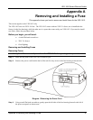
If the fans are not working properly, make sure the power connector is connected properly. Make sure the
fuse is not burnt-out. Replace the fuse if it is burnt out.
Contact your vendor if the fans do not work. Do not remove fans from the VES-1012. Only a qualified
distributor should remove or repair fans.
4 If the voltage levels are outside the range, take a screen shot of menu 24.12 and contact your vendor.
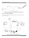
6.2 A PORT LED Does Not Turn On
Port LEDs show connections to the VDSL modem. It should blink when the system is transmitting/receiving
to/from the VDSL modem. If it is off, it means the link to the VDSL modem is down.
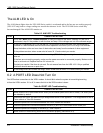
Table 6-4 PORT LED Troubleshooting
STEP CORRECTIVE ACTION
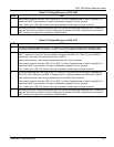
1 Make sure the VES-1000 Series switch VDSL port is enabled (refer to the User’s Guide). The VDSL ports
are disabled by default.
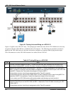
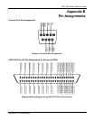
2 Check both the VDSL and phone line pin assignments shown in the Appendix – Pin Assignments to wire a
Telco cable to a Telco-50 connector.
3 Check the phone wire connections between the VDSL modem and the MDF.
4 Check the phone wire connections between the MDF(s) and VES-1000 Series switch USER port.
5 Check the phone wire mapping on the MDF(s) – see Chapter 3 .
6 Make sure the in-house wiring works and is connected properly (see section 6.4).