ADCP-75-210 • Issue 1 • March 2007
Page 65
© 2007, ADC Telecommunications, Inc.
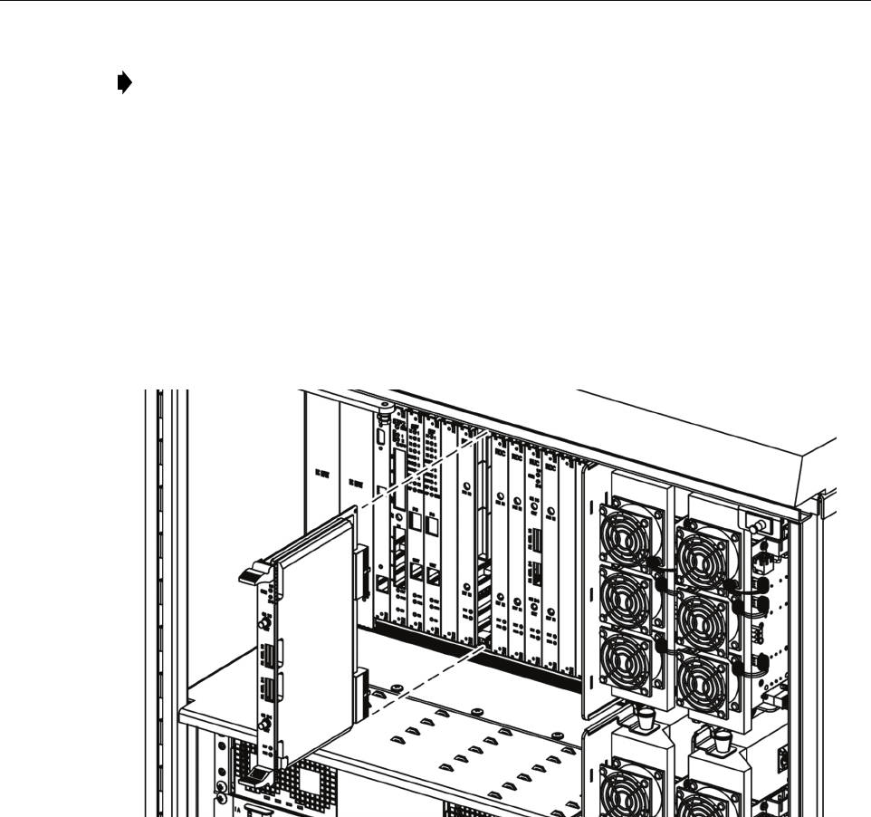
Use the following procedure to install an RUC2.X or RUC3 module (Figure 46):
1. Identify the designated chassis slot for the RUC module. This will be Slot 11 or 14. For
more information, see introductory text above.
2. Remove the RUC module from the anti-static packaging and orient for installation.
3. Slide the RUC module into the designated slot within the RAN cPCI chassis.
4. Lock the IEL handles on the top and bottom of the RUC module into the cPCI chassis and
tighten handle screws.
21233-AX
Figure 46. Installing an RUC Module
5. Using cable 1955000P079, connect the CH1/3 connector on the RUC module to either of
the following as appropriate:
– RF IN port on PAA1 if RUC module is in slot A2
– RF IN port on PAA3 if RUC module is in slot A5
6. Using cable 1955000P079, connect the CH 2/4 connector on the RUC module to either of
the following as appropriate:
– RF IN port on PAA2 if RUC module is in slot A2
– RF IN port on PAA4 if RUC module is in slot A5
Note: For a description of the module including function, controls, and indicators, refer to
Section 1.7.7 on Page 19. For a RAN chassis interconnection diagram, refer to Figure 40
on Page 58.


