Uninterruptible Power Supply Crestron CEN-UPS1250
Connectors, Controls & Indicators (Continued)
# CONNECTORS,
CONTROLS &
INDICATORS
DESCRIPTION
13 FILTERING LED
(1 green) Indicates the EMI and RFI noise
reduction circuit is active.
14 OUTLET BANKS
BANK 1 – DIGITAL DEVICES
(6) NEMA 5-15R female;
Grounded AC power outlets, switched;
Includes noise filtering and protection for
digital devices such as control systems,
power supplies, touchpanels and media
servers.
BANK 2 – DISPLAYS
(2) NEMA 5-15R female;
Grounded AC power outlets, switched;
Includes noise filtering and protection for
display devices such as LCDs, plasmas and
projectors.
BANK 3 – ANALOG DEVICES
(2) NEMA 5-15R female;
Grounded AC power outlets, delay switched;
Delayed turn on, adjustable from 0 to 10
seconds;
Includes noise filtering and protection for
analog devices such as Adagio
®
control
systems and tuners.
BANK 4 – HI-CURRENT DEVICES
(2) NEMA 5-15R female;
Grounded AC power outlets, delay switched;
Delayed turn on, adjustable from 0 to 10
seconds;
Includes noise filtering and protection for
high current devices such as amplifiers.
15 EXTERNAL BATTERY
(1) Connector for optional external battery,
sold by APC
2
.
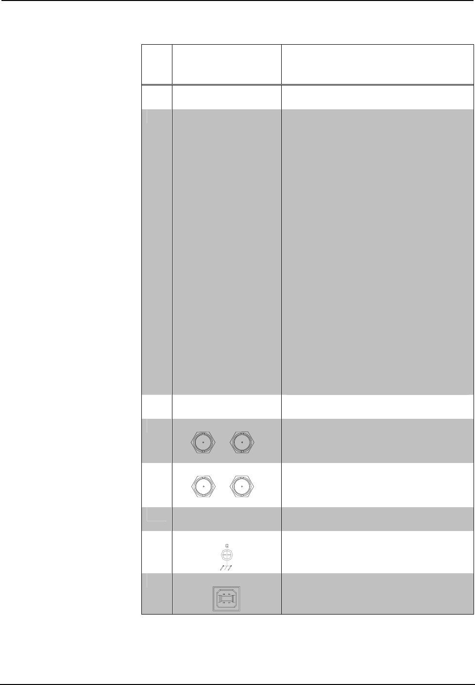
16
CABLE
IN
OUT
IN – (1) F-type coaxial, female;
Coaxial cable or antenna source connection.
OUT – (1) F-type coaxial, female, protected
TV/receiver or modem device connection.
17
SATELLITE
IN
OUT
IN – (1) F-type coaxial, female;
Coaxial cable or antenna source connection.
OUT – (1) F-type coaxial, female, protected
TV/receiver or modem device connection.
18
CIRCUIT BREAKER
BUTTON
Disrupts power to all outputs in case of an
overload condition, press to reset.
19
G
(1) Binding post, chassis ground lug.
20
SERVICE PORT
(1) USB Type B female;
Used for factory configuration only.
(Continued on following page)
8 • Uninterruptible Power Supply: CEN-UPS1250 Operations & Installation Guide – DOC. 6635A
