5
11/30/06
Manual No. 701-186M
Assembly Instructions
Land Pride
!
WARNING
Incorrect battery cable connections can damage vehicle’s
electrical system and cause battery cables to spark. Sparks
around a battery can result in a battery gas explosion and
personal injury.
• Always disconnect negative (black) battery cable before
disconnecting positive (red) cable.
• Always reconnect positive (red) battery cable to the
positive (+) postbefore reconnectingnegative (black)cable
to the negative (-) post.
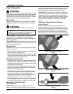
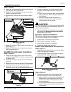
Relay Switch Installation
Refer to Figure 5:
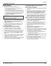
1. Attach 8-foot long red #10 wire to #2 red terminal at
winch motor.
2. Attach 8-foot long black #10 wire to #1 black terminal
at winch motor.
Winch Terminal Location
Figure 5
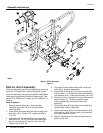
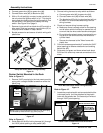
Refer to Figure 6:
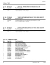
3. Route wiring along the Treker’s main frame, cross
over to the left side and continue routing wiring to the
relay switch location.
Winch Wiring Location
Figure 6
Attach #10 black wire
to this terminal
between two washers
Black
Washer
1
2
Attach #10 red wire
to this terminal
between two washers
Red
Washer
96" Black Wire
96" Red Wire
Main
Frame
Red and Black Wires
Crossing Over to Left
side of Vehicle
Plastic
Ties
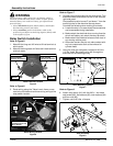
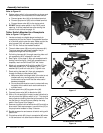
Refer to Figure 7:
4. Choose a mounting location for the relay switch. This
should be close to the electrical box on the vehicle’s
right side panel.
One possible location is over 2"and down 1"from the
mounting hole for the electrical box as shown.
Consider the following when making this choice.
a. Locate the relay in an area where the connections
can be accessed during installation.
b. Make certain the electrical wires running from the
winch and battery can reach the relay terminals.
c. Make certain the electrical wires are well clear of
any moving vehicle parts.
d. Also make certain they do not make contact with
any hot components such as the exhaust or
cylinder head.
5. Using the relay as a template, locate and drill four
1/4" dia. holes. Be careful not to drill through the
electrical box and existing wiring.
Relay Mounting Location
Figure 7
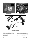
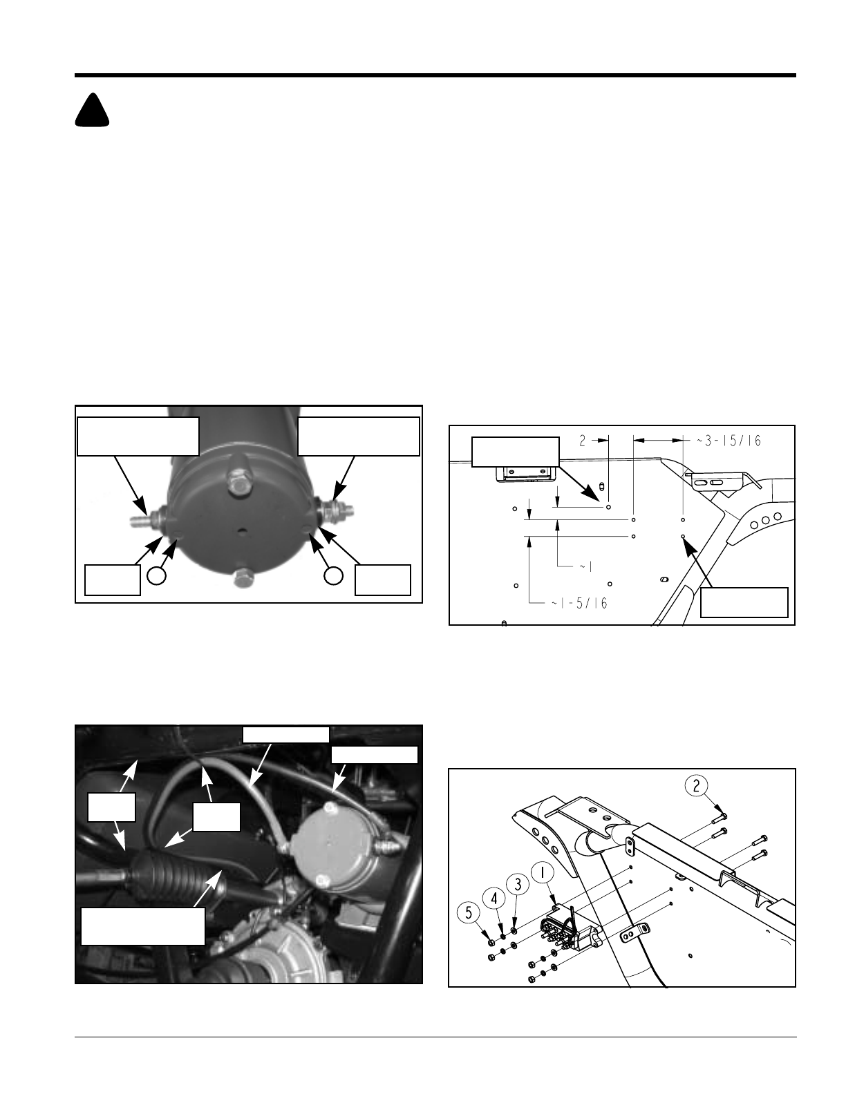
Refer to Figure 8:
6. Attach relay switch (#1) with four M6 x 1 hex head
cap screws (#2), flat washers (#3), lock washers (#4)
and hex nuts (#5).
7. Tighten nuts to 8 ft-lbs. of torque.
Relay Assembly
Figure 8
Electrical Box
Mounting Hole
Drill 1/4" Dia.
Hole (4-Places)