7
11/30/06
Manual No. 701-186M
Assembly Instructions
Land Pride
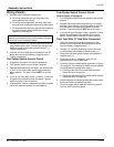
4. Connect green wire (#3) to green wire (#4).
5. Connect brown wire (#5) to black wire (#6).
6. With a 12-volt test light or meter, locate a wire that is
hot only when the ignition switch is “on”. This should
be a purple wire leading from the ignitionswitch. One
can be found in the wiring loom nearby the relay
switch. See Figure 20 on page 9.
7. Remove ring terminal from black wire (#7) and with a
blue scotch lock tap connector, connect wire (#7) to
the purple wire located in Step 6 above.
8. Bundle excess wire and secure all switch wiring with
plastic ties.
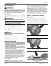
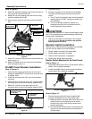
Clamp-On Rocker Switch Wiring Assembly
Figure 12
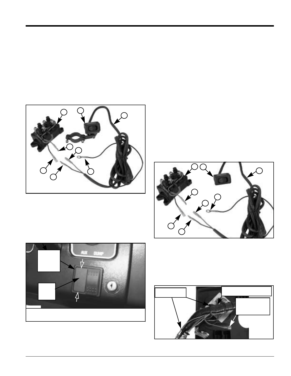
Rocker Switch Mounted in the Dash
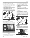
Refer to Figure 13:
1. Remove “AUX” panel plug in the instrument panel by
prying with a straight bladed screwdriver under the
panel plug.
Auxiliary Panel Plug Removal
Figure 13
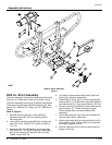
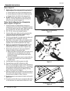
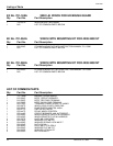
Refer to Figure 14:
2. Route ends (#3 & #5) of wiring harness (#1) through
the “AUX” panel opening to relay switch (#8).
8
2
5
7
3
4
6
1
21473
Panel
Plug
Aux
Mounting
Panel
NOTE: Inserta straightbladed screwdriverunder panelplug
as indicated by white arrows to pry panel plug out.
3. Connect wiring harness to relay switch as follows:
a. Connect green wire (#3) to green wire (#4).
b. Connect brown wire (#5) to black wire (#6).
c. The black wire (#7) with ring terminal end will not
be used. Cut off all excess extending from the
wiring harness.
4. Check and secure wiring harness routing:
a. Make sure there is enough slack for the steering
and all other vehicle functions to operate but not
so much that the wires could become entangled.
b. Do not allow the wires to come in contact with any
hot parts of the vehicle such as the exhaust or
cylinder head.
c. Secure wire harness to the Treker frame with
plastic ties.
5. Cut wire harness approximately 6" outside the “AUX”
panel opening to remove excess wire and existing
switch box (#2).
6. Strip newly cut green and brown wires back about
3/8 of an inch and crimp new red connectors to the
wires.
Dash Mounted Rocker Switch Wiring Assembly
Figure 14
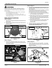
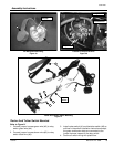
Refer to Figure 15:
7. Locate the purple wire with red connector behind the
instrument panel. It will be attached to the plastic
loom with two plastic ties. Cut ties and pull wire out
through “AUX” panel opening.
Plastic Loom Located Behind Instrument Panel
Figure 15
2
5
7
3
6
1
8
4
Cut Plastic Ties
(2-Places)
Purple Wire With
Red Connector
(Attach to Middle
Switch Terminal)
Plastic Loom Located
Behind Instrument Panel