8
Manual No. 701-186M 11/30/06
Land Pride
Assembly Instructions
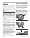
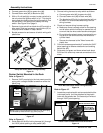
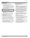
Refer to Figure 16:
8. Rotate rocker switch in the up position as shown and
make temporary connections to the rocker switch:
a. Connect green wire (#1) to the bottom terminal.
b. Connect purple wire (#2) to the middle terminal.
c. Connect brown wire (#3) to the top terminal.
9. DO NOT install rocker switch in the “AUX” panel
opening. It will be installed later after testing the
control circuit outlined on page 10.
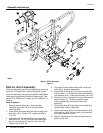
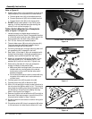
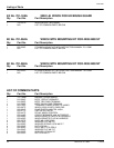
Tether Switch Mounted to a Receptacle
Refer to Figure 17 & Figure 18:
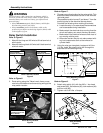
1. Locate and mark a suitable place to attach pin
receptacle (#10) to the Treker. One possible location
is in the kick panel under the seat. Make certain the
wire harness (#1) will reach relay switch (#8).
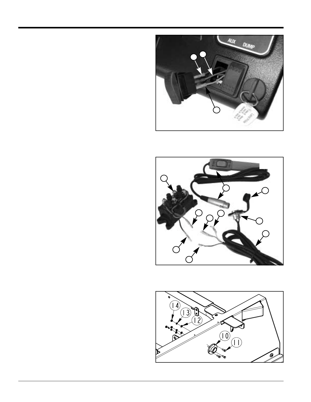
2. Drill 7/8" dia. hole at the marked location.
3. Thread rubber cover (#9) onto wiring harness (#1).
The cover must be positioned between the pin
receptacle flange and vehicle panel.
4. Pull wiring harness (#1) through mounting hole until
pin receptacle (#10) is seated in the hole.
5. See Figure 19 on page 9. Align pin receptacle with
locking notch facing up. Using pin receptacle as a
template, mark and drill three 5/32" dia. holes.
6. Attach pin receptacle (#10) with three M4-0.7 hex
head cap screws (#11), flat washers (#12), lock
washers (#13) and hex nuts (#14). Tighten nuts.
7. Route wiring harness (#1) from pin receptacle
through the body to relay switch (#8).
a. Make sure there is enough slack in the wire to not
interfere with any moving parts of the vehicle
functions but not so much that the wires could
become entangled.
b. Do not allow the wires to come in contact with any
hot parts of the vehicle such as the exhaust or
cylinder head.
8. Connect green wire (#3) to green wire (#4).
9. Connect brown wire (#5) to black wire (#6).
10. With a 12-volt test light or meter, locate a wire that is
hot only when the ignition switch is “on”. This should
be a purple wire leading from the ignitionswitch. One
can be found in the wiring loom nearby the relay
switch. See Figure 20 on page 9.
11. Remove ring terminal from white wire (#7) and with a
blue scotch lock tap connector; connect wire (#7) to
the purple wire located in Step 10 above.
12. Bundle excess wire and secure all switch wiring with
plastic ties.
13. Plug tether switch (#2) into pin receptacle (#9) when
in use and store in a safe location when not in use.
Rocker Switch Terminal Wiring
Figure 16
Rocker And Tether Switch Assembly
Figure 17
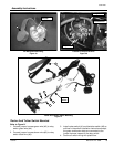
Pin Receptacle Assembly
Figure 18
1
3
2
5
7
6
1
8
4
9
10
3
2