6
Manual No. 701-186M 11/30/06
Land Pride
Assembly Instructions
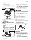
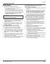
Refer to Figure 9:
8. Attach 96" black wire leading from thewinch motor to
relay terminal marked with the #1.
9. Attach 96" red wire leading from the winch to relay
terminal marked with the #2.
10. Secure motor wiring to the main frame with plastic
ties.
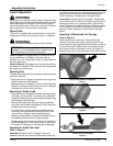
Relay Switch Terminals
Figure 9
11. Attach 36" red wire to relay terminal marked with the
positive sign (+).
12. Attach 36" black wire to the relay terminal marked
with the negative sign (-).
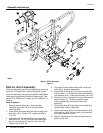
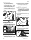
40 AMP Circuit Breaker Installation
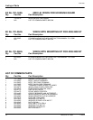
Refer to Figure 10:
1. Verify that the copper terminal stud on the circuit
breaker is labeled “BAT” and the silver terminal stud
is labeled “AUX”.
2. Install the red boot cover (#1) over circuit breaker
terminals.
3. Attach small ring terminal end of 10" red wire to the
connector stud on the circuit breaker labeled “BAT”.
4. Attach 36" red wire at the relay switch to the
connector stud on the circuit breaker labeled “AUX”.
40 AMP Circuit Breaker
Figure 10
To Battery (-) Post
36" Black Wire
2
+
1
--
To 40 Amp Breaker
36" Red Wire
ToWinchMotor
96" Red Wire
ToWinchMotor
96" Black Wire
To Operator Switch
Brown Wire
ToOperator Switch
Green Wire
Red Boot Cover
“BAT” Copper Color Stud
To Battery (+) Post
10" Red Wire
“AUX” Silver Color Stud
To Relay Switch
36" Red Wire
5. Close boot cover.
6. Choose a location for the 40-amp circuit breaker.
Consider the following points when making this
choice.
a. The 10" red #10 wire must reach from the positive
battery post to the “BAT” connection stud on the
circuit breaker.
b. The circuit breaker should be located in a
protected area that will not interfere with the
normal operation of the vehicle.
!
CAUTION
Do not connect the short 10" red wire to the battery at this
time. The connection to the positive battery post will be
the last step of installation.
7. Secure the 40-amp circuit breaker in the location
with plastic ties. Do not connect to the positive
battery post at this time.
Operator Switch Installation
There are four different switch arrangements available.
You will need to select one of the following:
1. Rocker switch mounted to the seat frame.
2. Rocker switch mounted in the dash.
3. Tether switch mounted to a receptacle.
4. Rocker and Tether switch mounted.
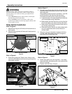
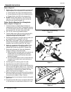
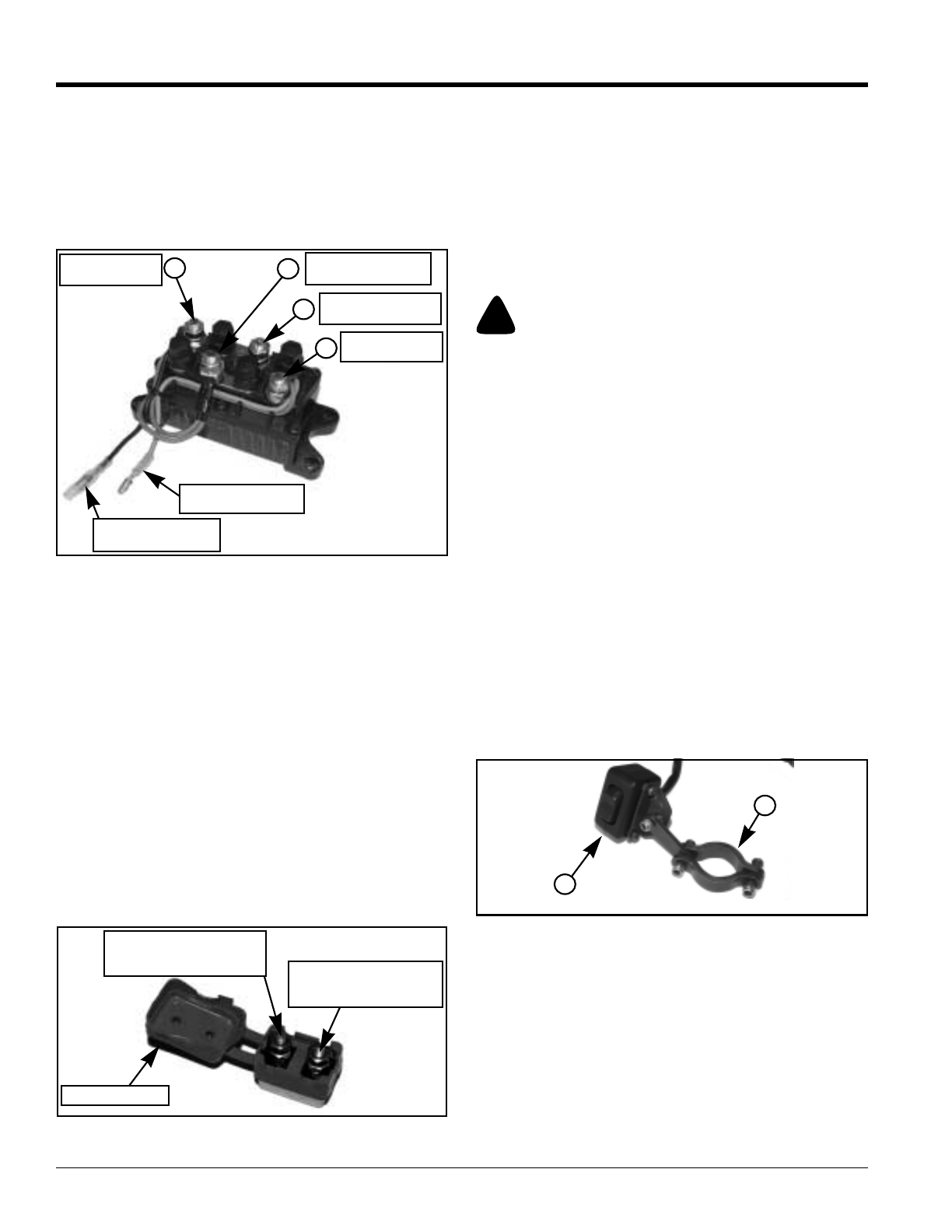
Rocker Switch Mounted to the Seat Frame
Refer to Figure 11:
1. Attach pipe clampfixture (#1) to rocker switch(#2) as
shown. Do not tighten hardware.
2. Locate a suitable location around seat and attach
rocker switch with clamping hardware.
Rocker Switch Mounting Clamp
Figure 11
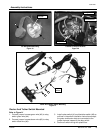
Refer to Figure 12:
3. Route wiring harness (#1) from the switch (#2)
through the bodywork to the relay switch (#8).
a. Make sure there is enough slack in the wire to not
interfere with any moving parts of the vehicle
functions but not so much that the wires could
become entangled.
b. Do not allow the wires to come in contact with any
hot parts of the vehicle such as the exhaust or
cylinder head.
1
2