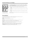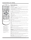
DIG•ANA
GUIDE
+•?
CH LIST
ABC
DEF
GHI
JKL
MNO
PQRS
TUV
WXYZ
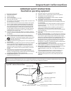
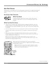
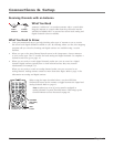
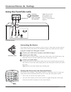
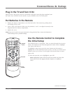
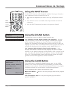
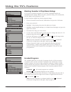
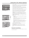
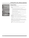
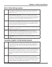
Using the Front/Side Jacks
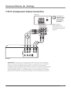
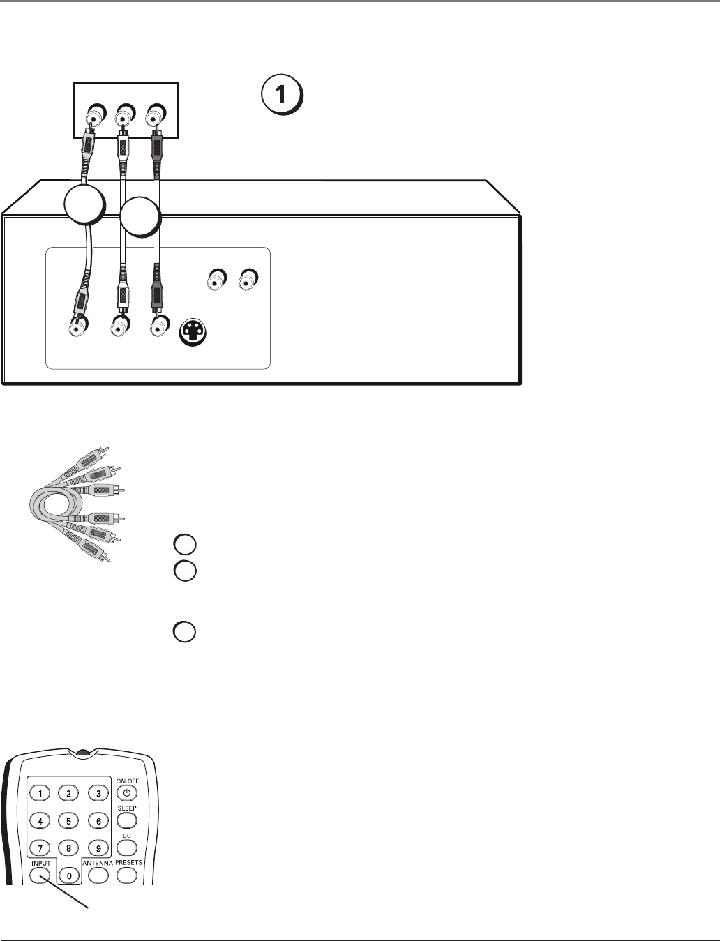
Connecting the Device
Thisconnectionallowsyoutoconnectadevicesuchasavideogameconsole,thathas
Audio/Videooutputjacks.Refertotheillustrationwhichusesaudioandvideocables.
Using the example of a video game console:
1. Connect your cable and/or antenna as described on page 5.
2. Connect your video cable.
Videocablesareusuallyyellow.ConnecttheVideocabletotheVIDEOjackonthe
front/sideoftheTVandtheVIDEOjackonthevideogameconsole.
3. Connect your audio cables.
Connecttheaudio(redandwhite)cablestotheRandLAUDIOjacksonthefront/
sideoftheTVandtotheaudiooutputjacksonthevideogameconsole.Justmatch
thecolors.
Note: Model 13V424T has VIDEO and L AUDIO jacks.
Audio/Video cables
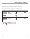
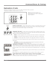
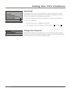
Viewing the Picture from the Connected Device
Thedeviceinthisexample,avideogameconsole,isconnectedtotheTV’svideoand
audiojackslocatedonthefront/sideoftheTV.Toviewthevideogameconsole:
1. TurnontheTVandthevideogameconsole.
2. PresstheINPUTbuttonontheremotecontroltotogglethroughtheVideoInput
ChannelsuntilFRNT isdisplayedinthechannelbanner.
VIDEO
OUTPUT
S-VIDEO
OUT
L R
AUDIO
L R
AUDIO
L AUDIO R
VIDEO
Front/side of TV
2
3
INPUT
button
Video Game Console
Note: This front/side
panel graphic is for
representation only.
Your TV’s jacks might be
different.
If necessary,
connect antenna
or cable to get a
picture. Go to page
5 for instructions.
Connections & Setup
10 Chapter 1