


10-Port 100BASE-FX and 20-Port 10/100BASE-TX Fast Ethernet Layer 2 Switching Modules Quick Start Guide
19
7
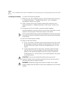
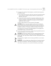
To engage the module with the backplane, use both hands to perform
the following steps:
a
Push firmly at the two ends of the front panel near the ejector handles
until you feel the module connectors make firm contact with the
backplane connectors.
b
Put your left thumb on the left or top ejector handle and your right
thumb on the right or bottom ejector handle. Simultaneously, push
the ejector handles in towards the front panel until each handle is
parallel with the front panel.
You feel a slight resistance as the connectors fully engage.
CAUTION: If there is too much resistance when you try to close the
ejector handles, the module backplane connector may not be aligned.
Forcing the module into place can damage the module connectors and
backplane connectors. If necessary, remove and reinsert the module,
ensuring that the connectors are properly aligned. Do not tighten the
spring-loaded screws to seat the module.
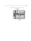
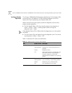
8
To secure the module in the chassis, tighten the spring-loaded screws to a
torque specification of 3 to 5 inch-pounds.
CAUTION: Verify that the module screws are properly aligned with the
threaded holes in the chassis. If the screws are not aligned when you
tighten them, you may strip the threads and make it impossible to secure
the module.
To ensure that you tighten screws to torque specification, use a torque
screwdriver.
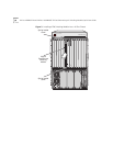
WARNING: To ensure adequate cooling airflow and continued product
safety agency compliance, install blank faceplates over all empty slots.
If the chassis is powered on, the module initialization process begins.