


20
10-Port 100BASE-FX and 20-Port 10/100BASE-TX Fast Ethernet Layer 2 Switching Modules Quick Start Guide
Verifying Module
Operation
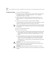
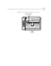
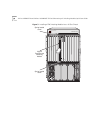
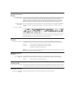
The 10-port 100BASE-FX FEN Switching Module has 10 Port Status LEDs
and the 20-port 10/100BASE-TX FEN Switching Module has 20 Port
Status LEDs. Each module has one Module Status LED.
Watch the LEDs during the system power-on diagnostics test to verify
proper module operation:
■ On the Module Status LED, the normal power-on test sequence is
Green – Yellow – Green – Flashing Green (while running the
diagnostic test) – Green
If the Module Status LED is Yellow after the diagnostics run, the module
has failed.
■ The Port Status LEDs are tested during the diagnostic test. The normal
test sequence is Yellow – Green – Off
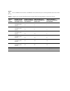
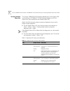
Table 11 describes LED colors and definitions.
Table 11
Module and Port Status LED Indicators
LED State or Color Definition
Module Status
Green Power is on (normal operation).
Flashing Green Diagnostics or software download is in
progress.
Yellow Diagnostic failure.
Off After initial insertion or module reset, the
LED remains unlit for approximately 3
seconds. Otherwise, an unlit LED
indicates that the module is not receiving
power.
Port Status
Green Port is enabled and link is up.
Flashing Green Port is receiving or transmitting packets.
Yellow Module or port is malfunctioning.
Off Port is disabled or link is down.