


2
10-Port 100BASE-FX and 20-Port 10/100BASE-TX Fast Ethernet Layer 2 Switching Modules Quick Start Guide
For information about the software features that these modules support,
see the:
■ CoreBuilder 9000 Implementation Guide
■ Command Reference Guide
■ CoreBuilder 9000 Release Notes for the Fast Ethernet and Gigabit
Ethernet Layer 2 Switching Modules
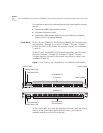
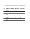
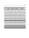
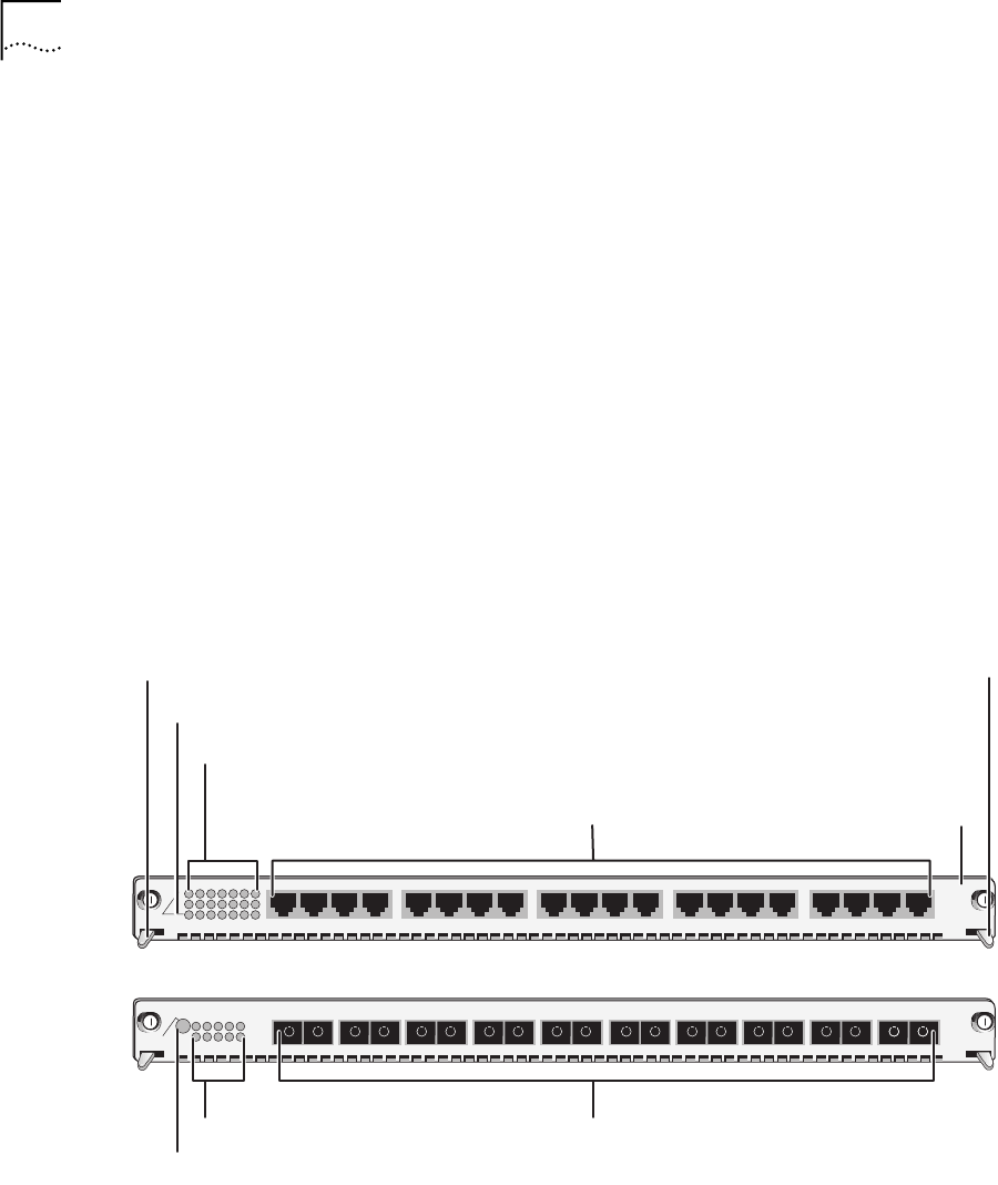
Front Panel
On the 10-port 100BASE-FX FEN Switching Module, the front panel ports
are numbered 1 through 10, as shown in Figure 1. The two 1-Gigabit
ports on the back of the module (not shown in Figure 1) are numbered
11 and 12.
On the 20-port 10/100BASE-TX FEN Switching Module, the front panel
ports are numbered 1 through 20, as shown in Figure 1. The two
1-Gigabit ports on the back of the module (not shown in Figure 1) are
numbered 21 and 22.
Figure 1
Front Panels for the 10/100BASE-TX and 100BASE-FX FEN Modules
In the 7-slot chassis, you install the modules horizontally with the LEDs at
the left. In the 8-slot chassis and the16-slot chassis, you install the
modules vertically with the LEDs at the top.
3CB9LF10MC
TX
RX
1
2
1
TX
RX
MOD STAT
2
3
4
6
7
8
9
5
1
0
TX
RX
3
TX
RX
4
TX
RX
5
TX
RX
6
7
TX
RX
TX
RX
8
TX
RX
9
TX
RX
10
3CB9LF20R
1
MOD STAT
2
3
4
5
6
7
14
1X
2X
3X
4X
5X
6X
7X
8X
9X
10X
11X
12X
13X
14X
15X
16X
17X
18X
19X
20X
3CB9LF20R
1
MOD STAT
2
3
4
5
6
7
14
1X
2X
3X
4X
5X
6X
7X
8X
9X
10X
11X
12X
13X
14X
15X
16X
17X
18X
19X
20X
Model number
Ejector handle
Module Status LED
Port Status LEDs
RJ-45 ports
Ejector handle
Module Status LED
Port Status LEDs
Fiber-optic ports
(SC connectors)
100BASE-FX
10/100BASE-TX