


2-4 CHAPTER 2: GETTING STARTED
CAUTION: Always follow Electrostatic Discharge
(ESD) procedures when installing an I/O Module.
1 If the Switch is connected to the network, turn off the
power and disconnect the switch from the main
power supply and the network.
2 Place the Switch on a flat, clean, hard, work surface.
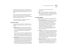
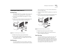
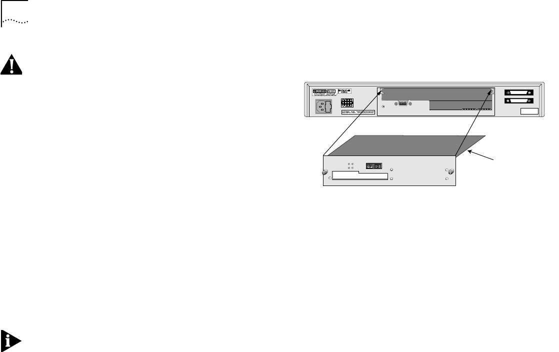
3 Locate and remove the blanking plate that covers the
slot. See Figure 2-2. Retain the blanking plate and the
screws for future use.
4 Use the guide rails within the Switch slot to align the
module. The location of the guide rails and the cor-
rect positioning of the plate is shown in Figure 2-2.
5 Slide the module into the slot without touching the
top or bottom of the circuit board, which positions
upside down on the plate. Ensure that the module is
pushed fully into the unit.
6 Use the thumb screws attached to the module to fix
the module firmly into place.
7 Connect the cable to the module port.
NOTE: For cable specifications see the guide that
came with your module.
8 Each end of the cable has a transmit (Tx) and receive
(Rx) connector. Connect the Rx connector to the
port’s Tx socket. Connect the Tx connector to the
port’s Rx socket. Do the same at the other end of the
connection.
9 Power up the switch. The link status LED turns green
once a valid connection is made.
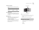
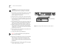
Figure 2-2 Inserting a Slide-in Module into a Switch 2000 TR
Token Ring-In-Fast Ethernet Module
Full Duplex
Port Status
Tx
Rx
Rx
Tx
Console Port
9600,8,1,N
3C510620
Reset
Board postions with
electronics facing down