


3-3
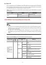
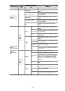
The mounting brackets can be attached to a switch for center, front, or rear mounting. You can choose a
proper position according to the actual requirements.
Table 3-2 shows the position support for the 3Com
Baseline Switch 2900 Family.
Table 3-2 Description of mounting position support for the 3Com Baseline Switch 2900 Family
Model Mounting position Description
3Com Baseline Switch
2920-SFP Plus
3Com Baseline Switch
2928-SFP Plus
Front or rear part of the chassis
See
Figure 3-4, and Figure
3-5.
3Com Baseline Switch
2952-SFP Plus
Front or rear part of the chassis
See Figure 3-6, and Figure
3-8.
3Com Baseline Switch
2928-PWR Plus
3Com Baseline Switch
2928-HPWR Plus
Front, center, or rear part of the
chassis
See
Figure 3-6, Figure 3-7,
and
Figure 3-8.
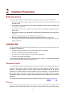
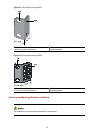
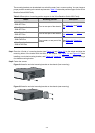
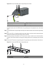
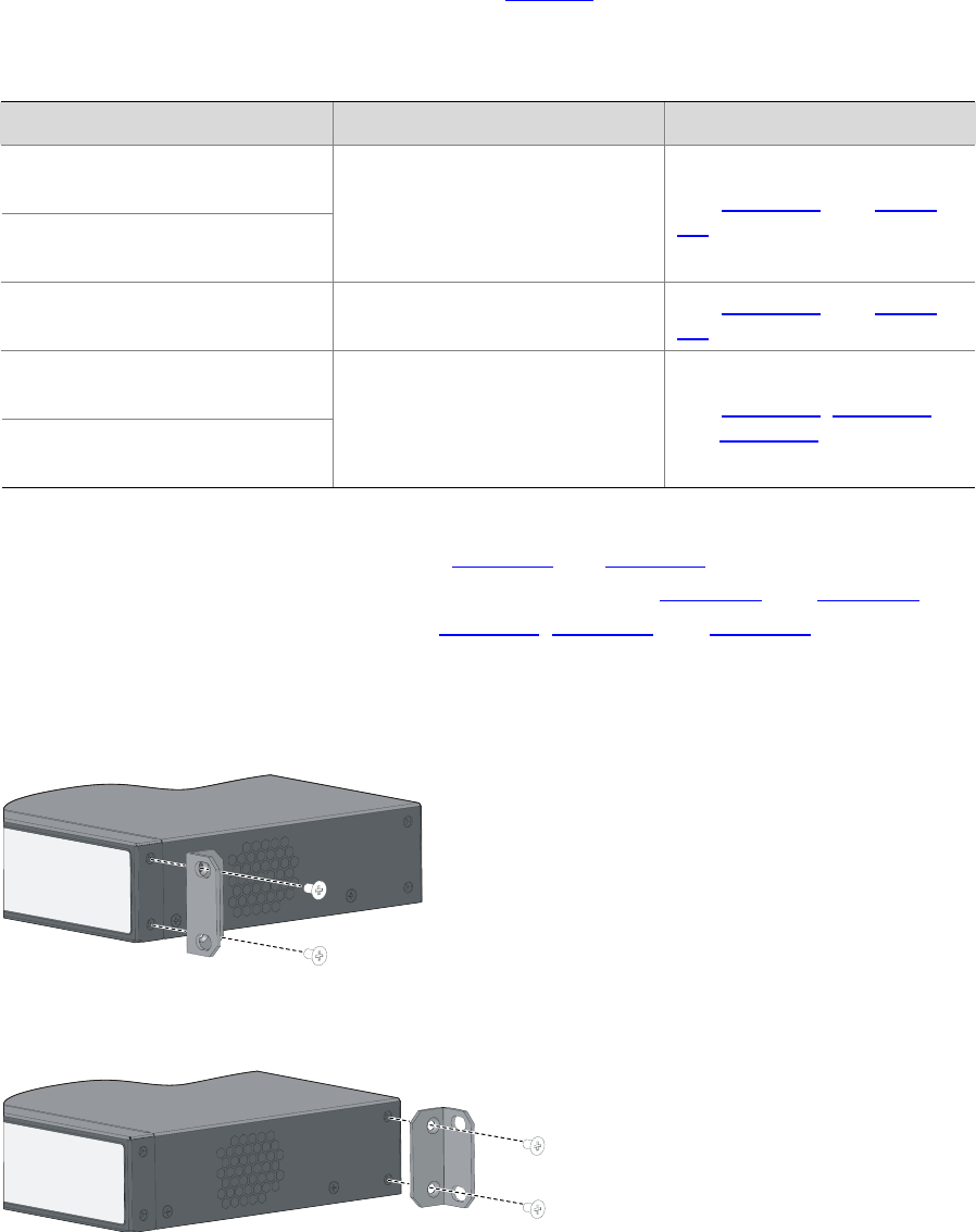
Step1 Place the L2 side of a mounting bracket (see
Figure 3-2 and Figure 3-3) to the switch and align the
mounting holes of the bracket with the holes of the chassis. See
Figure 3-4 and Figure 3-5 when
installing a two-holed mounting bracket, and
Figure 3-6, Figure 3-7, and Figure 3-8 when installing a
four-holed mounting bracket.
Step2 Fasten the screws.
Figure 3-4 Install a two-holed mounting bracket on the chassis (front mounting)
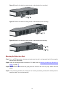
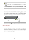
Figure 3-5 Install a two-holed mounting bracket on the chassis (rear mounting)