


3-6
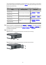
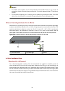
Mounting the Switch on a Workbench
In many cases, standard 19-inch cabinets are not available. Therefore, switches are often placed on
clean workbenches. To place the switch on a workbench, follow these steps:
Step1 Place the switch with bottom up carefully, and then clean the round holes on the chassis bottom with dry
cloth.
Step2 Attach the rubber feet to the four round holes on the chassis bottom.
Step3 Place the switch with upside up on the workbench.
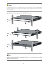
During the operation, you simply need to:
z Make sure that the workbench is flat and sturdy.
z Ensure good ventilation and a space of 10 cm (3.94 in.) around the chassis for heat dissipation.
z Avoid heavy objects on the switch.
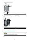
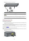
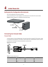
Connecting the PGND Cable
z Correctly connecting the switch PGND cable is crucial to the lightning protection and
electromagnetic susceptibility (EMS) of a switch.
z The power receptacles and grounding terminals in this section are for illustration only.
The power input end of the switch is connected with a noise filter, whose central ground is directly
connected to the chassis, forming the so-called chassis ground (commonly known as PGND). This
chassis ground must be securely connected to the earth so that the faradism and leakage electricity can
be safely released to the earth, enhancing the EMS capability of the switch.
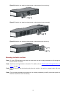
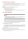
When a Grounding Strip is Available
When a grounding strip is available at the installation site, attach one end of the yellow-green PGND
cable of the switch to the grounding screw on the grounding strip (the grounding screw and the
grounding hole are on the rear panel of the switch and are marked with a grounding sign). To do this,
follow these steps:
Step1 Remove the grounding screw from the rear panel of the switch chassis.
Step2 Put the supplied OT terminal of the PGND cable on the grounding screw.
Step3 Fasten the grounding screw, which is attached with the OT terminal of the PGND cable, into the
grounding screw hole with a screwdriver.