


3-8
z The PGND cables supplied with the 3Com Baseline Switch 2900 Family do not provide OT
terminals at the ends connecting the grounding strip. You need to prepare proper OT terminals by
yourself.
z The fire main and lightning rod of a building are not suitable for grounding the switch. The PGND
cable of the switch should be connected to the grounding device for the equipment room.
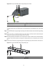
Where a Grounding Conductor Can be Buried
When there is no grounding strip, but an area with exposed earth is available nearby where a grounding
conductor can be buried, hammer a 0.5 m (1.64 ft.) or longer angle iron or steel tube into the earth. The
angle iron should have a dimension no less than 50 × 50 × 5 mm (1.97 × 1.97 × 0.20 in.) and the steel
tube should have a wall thickness no less than 3.5 mm (0.14 in.) and be zinc-coated. Weld the
yellow-green PGND cable to the angel iron or steel tube and treat the joint for corrosion protection.
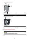
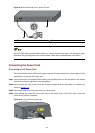
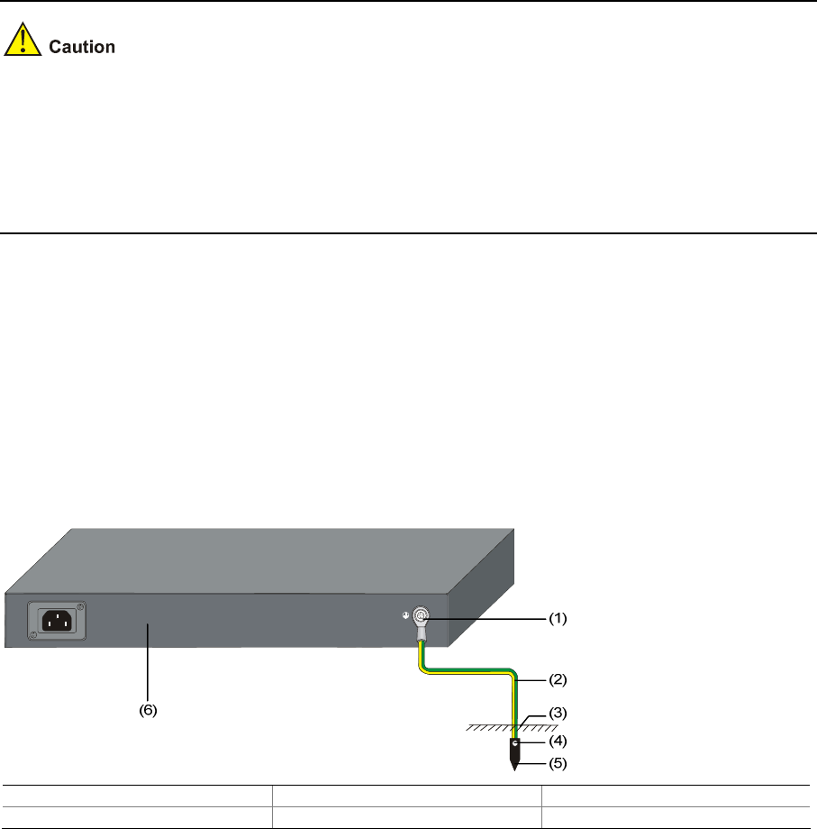
Figure 3-12 Ground the switch by burying the grounding conductor into the earth
(1) Grounding screw (2) PGND cable (3) Earth
(4) Joint (5) Grounding conductor (6) Switch rear panel
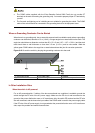
In Other Installation Sites
When the switch is AC-powered
For an AC-powered switch, if neither of the above-mentioned two conditions is available, ground the
switch through the PE wire of the AC power supply. Make sure the PE wire is well connected to the
ground at the power distribution room or AC transformer side, the switch PE terminal and the PE wire
are well connected, and the three-wire input cable of the PGND cable is used for the power supply cable.
If the PE wire of the AC power supply is not grounded at the power distribution room or AC transformer
side, report the problem and make reconstructions.