2 INDEX
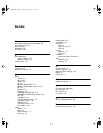
I
IBM cluster controller 1-7
installing
in a rack
1-4
on a tabletop 1-3
stacking with brackets 1-4
ISDN
acquiring telecommunication services
A-9
cable 2-20
German BRI services A-9
information sheet A-2
North American BRI services A-1
phantom power A-9
provisioning tables A-3
SPIDs A-7
L
LEDs
meanings
4-3
normal 4-1
loading software, troubleshooting 4-2
M
memory
installing
3-2
upgrading 2-1, 3-1
model features 2-1
modem cable 2-6
modem eliminator 1-5
monitor utility 2-3
mounting
in a rack
1-4
on a tabletop 1-3
stacking units 1-4
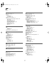
N
National switch, ordering A-6
network supplier support B-3
NT1 1-6, A-8
O
online technical services B-1
P
PC cable 2-4
PhantomPower parameter A-9
physical specifications 2-21
power supply redundancy 1-10
power, turning off 1-12
R
rack-mount installation 1-4
rack-mount kit 1-3
Redundant Power System (RPS)
attaching
1-10
cable 1-10
required equipment 1-1
returning products for repair B-5
RS-232 cable
RS-232 to RS-232 DCE
2-17
RS-232 to RS-232 direct connect 2-18
UNIVERSAL to DCE 2-15
UNIVERSAL to direct connect 2-16
S
serial connector
active ports
2-1
cabling information 1-7
DCE-like mode 1-8
DTE mode 1-8
shipping carton contents 1-1
shutting down 1-12
Siemens EWSD switch, ordering A-7
software recovery 1-2
specifications 2-21
SPIDs A-7
stacking units with mounting brackets 1-4
STP
cable
2-7
connector 2-7
switches
AT&T 5ESS
A-4
AT&T 5ESS (custom) A-5
DMS 100 A-6
National A-6
Siemens EWSD A-7
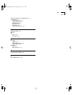
T
tabletop installation 1-3
technical support
3Com URL
B-1
bulletin board service B-1
fax service B-2
network suppliers B-3
product repair B-5
using CompuServe B-3
terminal
configuration settings
1-11
terminal cable 2-5
token ring
cables
2-6, 2-7
connectors 2-6, 2-7
SS2TRHWBook Page 2 Monday, May 5, 1997 3:11 PM


